AWR

RF / Microwave Design & Analysis

A comprehensive electronic design automation (EDA) platform for developing RF/microwave products.
See What The Industry-Leading RF/Microwave Design Platform Can Do For You

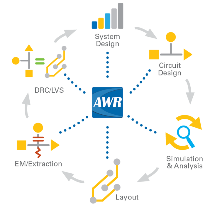
AWR Flow
Key Capabilities

Comprehensive RF Design, Analysis & Implementation Environment

A powerful and intuitive user interface ensures optimal engineering productivity with smart, customizable design flows for today’s high-frequency semiconductor and PCB technologies.

Unmatched Speed & Accuracy

Integrated system, circuit, and EM simulation technologies provide fast and accurate analysis of device performance before prototype manufacturing and test, saving development time and costs.

Automation Built on Experience

Design-flow automation connects simulation models, third-party tools, and layout to manufacturing processes, from early concept exploration through engineering signoff.

The AWR Design Environment platform is highly integrated and brings together most aspects needed for RF design. The software has a user friendly interface that enables designers to have full control of the tool.

ot contrib qorvo
APPLICATIONS

Solve Your Toughest Design Challenges

Focused on all aspects of RF/Microwave design, AWR Design Environment provides the comprehensive platform you need. No matter the challenge, we have targeted solutions and resources to help you resolve them .

Amplifiers

Address your bandwidth, efficiency, and linearity challenges head-on with advanced harmonic-balance simulation as well as powerful load-pull analysis and impedance-matching circuit synthesis.

Antennas

Design, optimize, and integrate antennas/arrays with certainty using the powerful AWR EM technologies to simulate antenna metrics such as gain, return loss, radiation efficiency, and currents.

Communications

Confidently develop and integrate 5G enabling technologies with the AWR proprietary, phased-array generator, standard-specific 5G signal waveforms, and virtual RF modulated test benches.

Filters

Leverage our integrated planar MoM, 3D FEM, and EM solvers to design complex filter solutions with the low passband insertion loss and the sufficient stopband rejection needed.

Passives

Take advantage of increased power-handling capabilities and drive successful passive component design focused on reducing device footprint, costs, and associated insertion losses.

Radar

Accurately represent signal generation, transmission, phased-arrays, T/R switching, clutter, noise, jamming, and signal processing, to tackle the design challenges for modern radar systems.
PRODUCTS

Solutions for All Aspects of RF/Microwave Design

MWO screenimage

Microwave Office

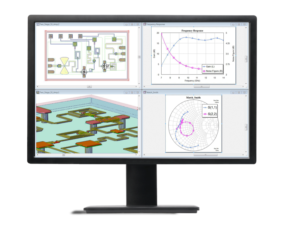
Circuit design software that delivers accurate simulation for RF/microwave product development

Leading manufacturers use Microwave Office circuit design software to accelerate product development of high-frequency electronics. The intuitive interface, innovative design automation, and powerful harmonic-balance circuit simulation ensure greater engineering productivity and accelerated design cycles. RF-aware layout, high-frequency models, design automation, and powerful HB simulator ensure greater engineering productivity and speed up design cycles for today’s most challenging applications

What Our Users Have to Say

Every designer faces a choice during the design cycle: do I believe the simulation results displayed by the software, or not? I trusted the predictions and, thanks to AWR Microwave Office, the new design worked perfectly. The performance we achieved is unlike any other MMIC ever produced.
Key Features
  • Schematic/Layout – Synchronous schematic/layout design entry with industry-leading tuning
  • APLAC – Linear and nonlinear harmonic-balance circuit simulation
  • EM Analysis – Fully integrated electromagnetic (EM) with AWR AXIEM and AWR Analyst tools
  • Load-Pull – State-of-the-art load-pull analysis with harmonic and video-band tuning
  • Stability – New fast, rigorous loop circuit envelope analysis for multi-stage and balanced amplifier stability
  • DRC/LVS – Design rule checking/layout vs. schematic
VSS screenimage

Visual System Simulator

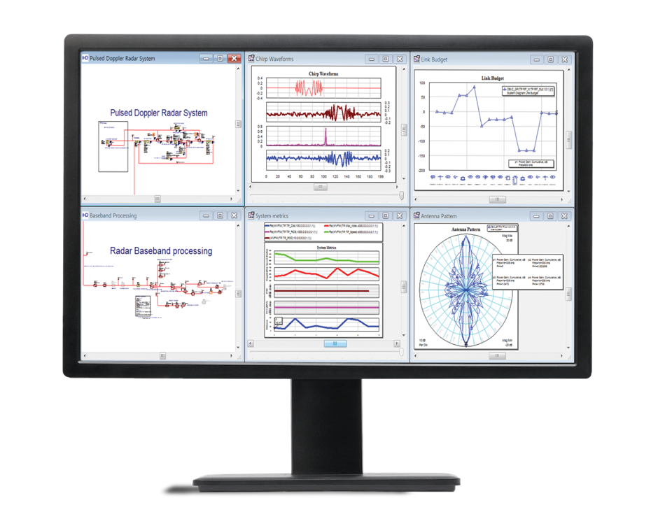
System simulation and modeling for wireless communications and radar system design

Visual System Simulator™ (VSS) RF/wireless communications and radar system design software supports VSWR-aware modeling of RF and DSP blocks, providing time-domain, frequency-domain, and circuit-envelope analyses. With VSS, Tx/Rx designers are able to develop and optimize system architectures and determine component specifications for best overall performance. Users can simulate system metrics such as BER and EVM with pre-configured and user-defined virtual test benches, as well as identify the source of spurious products and other system impairments.

What Our Users Have to Say

The unique, open, and integrated environment of VSS enabled us to study the effects of the nonlinear distortion on our communications link margin using real digital modulated analog waveforms.

Key Features
  • Behavioral Models – Impedance mismatch incorporating the impact of component VSWR on system performance
  • Circuit Envelope – Analysis of digitally-modulated RF circuits including EVM, BER, and adjacent channel power ratio (ACPR) simulations
  • Planning/Analysis Tools – Cascaded RF measurements, frequency planner (option), and spurious analysis
  • Co-Simulation – With Microwave Office circuit design software
  • Test Benches – Wireless standards including 5G, LTE, narrowband internet of things (NB-IoT), and more
  • Libraries – Radar and 5G signals and waveforms, inclusive of test benches
MWO screenimage

Analyst

Finite-element method (FEM) electromagnetic (EM) analysis for 3D structures

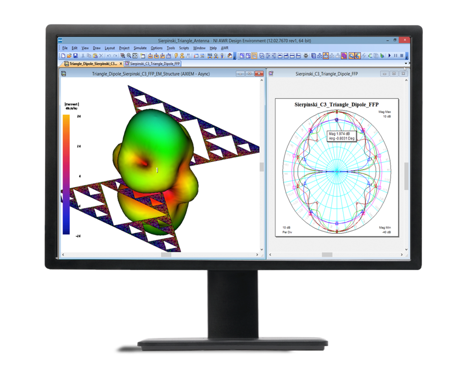
Analyst™ 3D FEM EM simulation and analysis simulator accelerates high-frequency product development from early physical design characterization through to full 3D EM verification. The advanced solver technology provides fast and accurate analysis of 3D structures/interconnects found in today’s complex, high-frequency electronics.

What Our Users Have to Say

We chose AWR software because of the proven success of AntSyn and Analyst. The resulting designs worked from the very start and removed the iteration and experimentation usually required in antenna design efforts.
Key Features
  • EXTRACT – Schematic-driven EM extraction technology/design flow
  • Layout/Drawing Editor – 2D and 3D construction and views
  • Unique FEM Solver – Proprietary, full-wave direct and interative solvers
  • Advanced Meshing Technology – Automatic, adaptive 3D volumetric tetrahedron-based meshing
  • Multiple Sources – Numerous excitations for ports
  • Fast Effective Visualization – 2D- and 3D-field visualization, as well as results post-processing
  • Parametric Studies – Optimization, tuning, and yield analysis
  • High Performance Computing (HPC) Enabled – Multi-core configurations and asynchronous simulation

Axiem

3D planar electromagnetic (EM) analysis for S-parameter extraction and design verification

AXIEM 3D planar method-of-moments (MoM) EM analysis simulator addresses passive structures, transmission lines, large planar antennas, and patch arrays. AXIEM software delivers the accuracy, capacity, and speed designers need to characterize and optimize passive components on RF PCBs, modules, LTCCs, MMICs, RFICs, and antennas.

What Our Users Have to Say

AWR Microwave Office, AXIEM, and Analyst were pivotal in the analysis of circuit parasitics, tuning towards optimization, and analysis of the effects of environmental disturbance, enabling us to produce an overall more robust product.
Key Features
  • Schematic/Layout – Synchronous schematic/layout design entry with industry-leading tuning
  • APLAC – Linear and nonlinear harmonic-balance circuit simulation
  • EM Analysis – Fully integrated electromagnetic (EM) with AWR AXIEM and AWR Analyst tools
  • Load-Pull – State-of-the-art load-pull analysis with harmonic and video-band tuning
  • Stability – New fast, rigorous loop circuit envelope analysis for multi-stage and balanced amplifier stability
  • DRC/LVS – Design rule checking/layout vs. schematic
WHATS NEW

AWR Design Environment v22.1

Highlights
microwave virtuoso

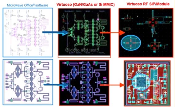
Allegro to Virtuoso Platform
Import Designs into Virtuoso Platform for Multi-Technology Integration
awr allegro

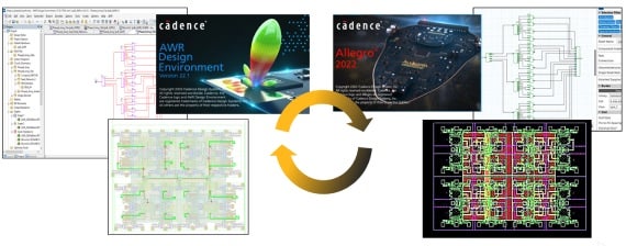
AWR to Allegro Platform
Integrate Your RF IP into PCB Manufacturing Layout
simulation green

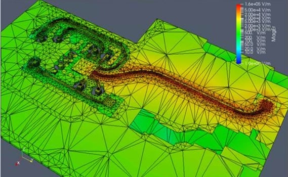
AWR & Multiphysics Analysis
With Clarity 3D Solver & Celsius Thermal Solver Integrations

Version Control

Version control supports collaboration between multiple designers and maintains a revision history of design data. The latest release adds additional functionality to the version control features for effectively managing group design of complex, multi-function projects across many different technologies.

EMX 3D Planar Solver Integration

Run EM analysis on silicon Virtuoso PDK RF circuit designs from within the AWR platform using the EMX Planar 3D Solver. The EMX solver is extremely efficient and accurate at solving silicon IC structures and is widely supported by foundries. New Virtuoso PDKs enabled for Microwave Office software can include foundry-approved EMX passive components.

Hybrid Optimizer

This release introduces a new hybrid optimizer method combining the best performance of several optimizers to produce a top-performing algorithm on a very wide range of problems.

VSS File Expansion for Hardware Data Sharing

New data file utilities simplify the exporting/importing of waveform data for applications such as DPD, DUT evaluation, and communications receiver testing, supporting more efficient capture of waveforms from test hardware and other applications into AWR Visual System Simulator (VSS) communications and radar systems design software. To facilitate signal demodulation in VSS software, transmitter-generated signal properties blocks can save and re-apply propagated properties from and to any signal in VSS software.

Enhanced Spectre RF Option Integration and Spectre Netlist Import Utility

Microwave Office software now supports the easy setup of Spectre RF Option simulation in the AWR Design Environment platform with a new Circuit Options dialog box Spectre tab for embedded Spectre netlists in an AWR project. A new utility script allows users to import Spectre netlist blocks, creating schematic symbols that can be simulated with an analysis using a VSS testbench or embedded into an AWR project (network) for RFIC/module co-design.

Synthesizer

The Component Synthesis Wizard now supports the synthesis of several new types of passive microwave structures to be implemented in microstrip transmission line structures. The Mixer and Multiplier Synthesis Wizard is now available to all users developing microwave frequency conversion devices (requires nonlinear simulation license).

TECHNOLOGIES

Multi-Fabric Implementations to Meet Your Design Requirements

AWR Design Environment is built to support your RF/Microwave designs across multiple fabrics. From on chip RF structures to full RF board solution we have the technology you need to match your needs.
technologies rf pcb menu 0519

RF PCBs

Simulation and design flow technologies for high-frequency printed-circuit board (PCB) development.
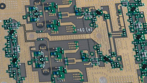
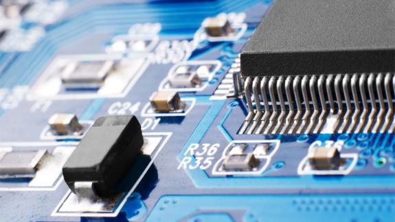
To support increasing functionality, printed-circuit boards (PCBs) use more complex board structures designed for a range of specialized applications. Offering a layout-driven design methodology for complex RF PCBs, AWR software supports accurate modeling of PCB transmission media from the RF signal path to digital control and DC bias lines. Circuit/system and electromagnetic co-simulation provides first-pass design success with complete PCB analysis of surface-mount components, interconnecting transmission lines, and embedded and distributed passive elements, as well as EM verification.

modules technologies page 0419

RF Modules

Simulation and design flow technologies that support multi-chip module product development.
RF modules combine multiple integrated circuits (ICs) into a single package, offering a large amount of functionality in a small space. This level of device integration can be an engineering challenge, requiring design teams to model the electrical behavior of many different technologies, including interconnects (transmission lines) and embedded distributed components, as well as RF, analog, and digital components. Electronic design automation (EDA) software is critical for achieving simulation results that are closely matched to the final results.

mmics technologies page 0419

MMICs that Matter

Front-to-back simulation and design flow technologies support MMIC product development
III-V semiconductor devices offer superior RF performance for mobile devices, communications infrastructure, and aerospace applications. Achieving optimal performance requires reliable circuit simulation, EM verification, communication test benches, and a design flow that links electrical design to physical realization. AWR software offers a leading front-to-back monolithic microwave integrated circuit (MMIC) design flow with an innovative user interface and complete integration of design entry, simulation, and physical design tools that enhance engineering productivity and ensures first-pass success.

technologies rf pcb menu 0519

RFIC

Simulation and design flow technologies supporting RF integrated circuit (RFIC) intellectual property (IP) development.
The demand for wireless connected devices is driving the need for a new generation of high-performance, cost-sensitive silicon products. AWR software provides communications integrated-circuit (IC)​ designers with a platform to develop complete small-scale RFICs or RF front ends for large-scale RFICs from system- to transistor-level design. The software offers native or third-party schematic/layout entry and fully-integrated electromagnetic (EM) extraction for interconnects and on-chip passive components and enables co-simulation with frequency-domain harmonic balance (HB) and transient time-domain circuit analysis.

Free Trial

EMA Design Automation