Discrete electronics, such as automotive circuitry, can be highly susceptible to noise induced by ESD or EMI. To ensure functionality in the field, these circuits require thorough and detailed worst-case analysis; however, the level of detail required makes this extremely time consuming. OrCAD PSpice Designer allows you to dynamically adjust the amount of granularity throughout the entire simulation with the schedule command, achieving the necessary detail in the area of interest while reducing simulation run time.
This how-to provides step-by-step instructions to implement the Schedule Command in worst-case transient simulations in PSpice.
How-To Video
Creating the Design
Step 1: Open OrCAD PSpice Designer and complete the desired circuit configuration.
Note: Worst-case analysis is typically performed through transient analysis with a pulse/stimulus as the voltage source. For an accurate automotive simulation and analysis, utilize a specialized source from the AEi Power IC Model Library which incorporates realistic noise into the power source.
- Delete the existing source in the circuit.
- Select Place > Part from the menu.
- Click the Add Library button and browse to the location of the downloaded Power IC Model Library.
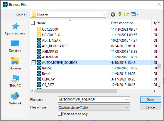
- Select AUTOMOTIVE_SOURCE.olb.
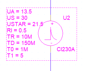
- Replace the power source with the CI230A from the library.
Configuring the Simulation
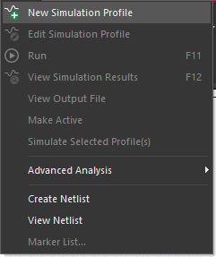
Step 2: Select PSpice > New Simulation Profile from the menu or the New Simulation Profile button from the toolbar.
Step 3: Name the simulation AUTO_5V_TRANS and click Create.
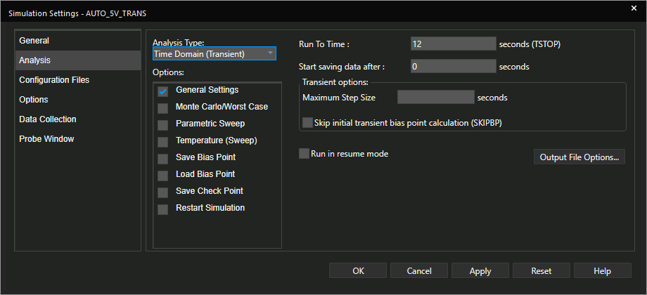
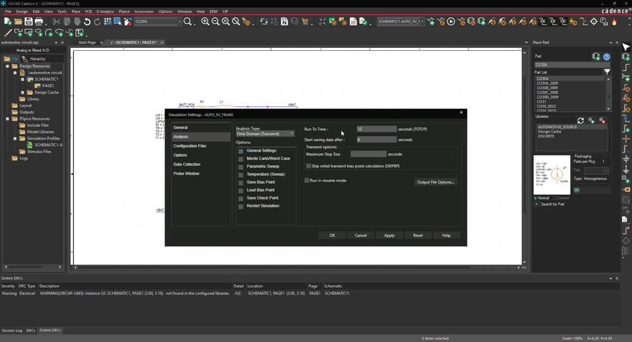
Step 4: Set the Analysis Type to Time Domain (Transient) and the Run To Time to 12 seconds.
Note: In worst-case analysis, detail is achieved by reducing the maximum step size for the entire simulation, so calculations are made more frequently. This is unnecessary if the majority of the simulation is at steady-state. The schedule command allows you to dynamically adjust the step size to increase detail on only the area of interest.
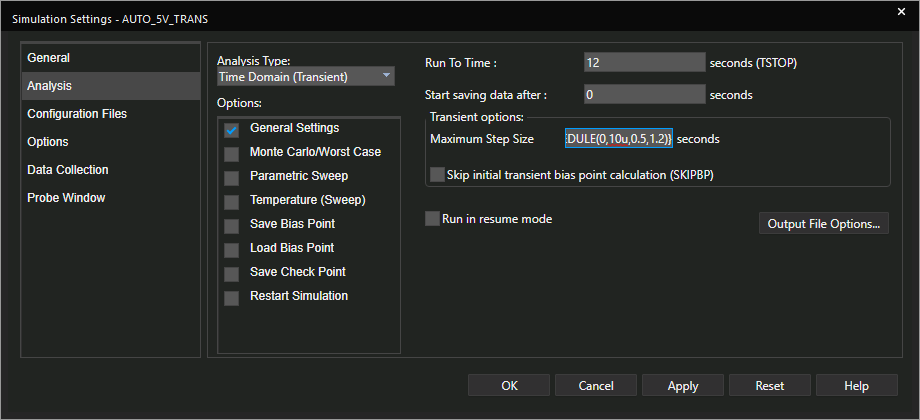
Step 5: Under Maximum Step Size, type {SCHEDULE(0,10u,0.5,1.2)}.
Note: This will set the maximum step size to 10 microseconds at the start of the simulation, then change it to 1.2 seconds at the 0.5-second mark. The format for the schedule command is as follows: {SCHEDULE(time, step size, time, step size)}. These is no limit on defining time and step size.
Step 6: Click OK.
Note: If using a source from the AEi Power IC Library, the library will need to be configured before running the simulation.
- Select Configuration Files from the sidebar in the simulation window.
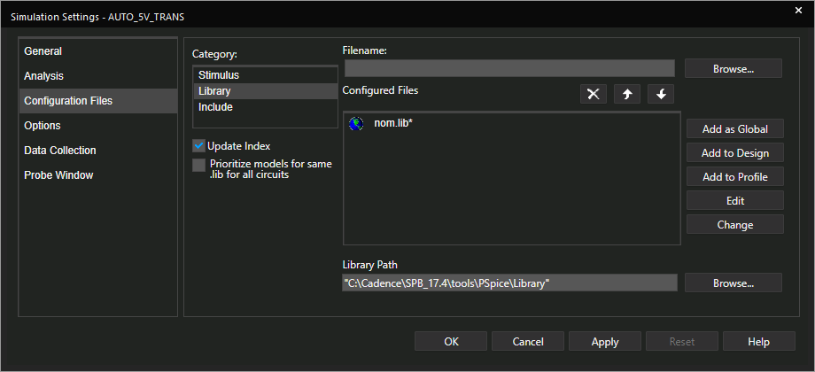
- Under Category, select Library.
- Click Browse. Browse to the location of the downloaded Power IC Model Library, select automotive_sources_encrypted.lib.
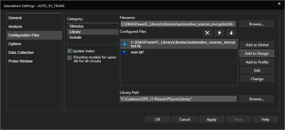
- Click Add to Design.
Performing the Simulation
Step 7: Select PSpice > Run from the menu or the Run button from the toolbar.
Note: If you receive a “Large Data File” warning, the simulation will still complete; however, you can resolve the warning by shortening the time of interest.
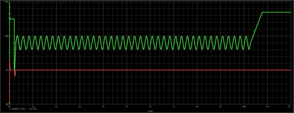
Step 8: View the results in the PSpice window.
Note: The schedule command can also be used to dynamically adjust the following:
- Accuracy/Tolerance of Voltage and Current (RELTOL, ABSTOL, VNTOL)
- Minimum Conductance (GMIN)
- Number of Iterations (ITL4)
Wrap Up & Next Steps
Achieving the required accuracy for detailed, worst-case analysis of sensitive, discrete electronics can be time-consuming. Reduce simulation run time without sacrificing detail by dynamically adjusting granularity throughout the simulation with the schedule command in OrCAD PSpice. Check out AEi Power Model Library for accurate automotive simulation models and get your free trial of PSpice to efficiently simulate your designs.
