In today’s markets, PCB designs often need to incorporate rigid flex or strict component placement to adhere to shrinking mechanical requirements. These types of complexities require more advanced 3D analysis and clearance checking as the likelihood of collision is higher and any Z-axis delay can have a detrimental effect on design performance. With the new 3DX canvas in Allegro X you can quickly and easily perform advanced 3D analysis to ensure the success of the final assembly.
This quick how-to will provide step-by-step instructions on how to analyze a PCB in 3D with 3DX in Allegro X Venture.
To follow along, download the files located above the table of contents.
How-To Video

Opening the 3DX Canvas
Step 1: Open the provided design in Allegro X Venture Layout.
Note: This feature is available in any tier of Allegro X.
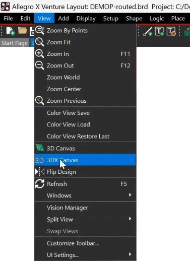
Step 2: Select View > 3DX Canvas from the menu or the 3DX button from the toolbar.
Note: The 3DX canvas is opened. This is a similar view to that of the Allegro Free Viewer.
Navigating the 3DX Canvas
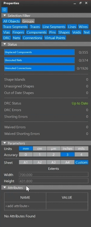
Step 3: View the Properties panel. This shows the number of unplaced components, DRC errors, and parameters such as sheet size and units.
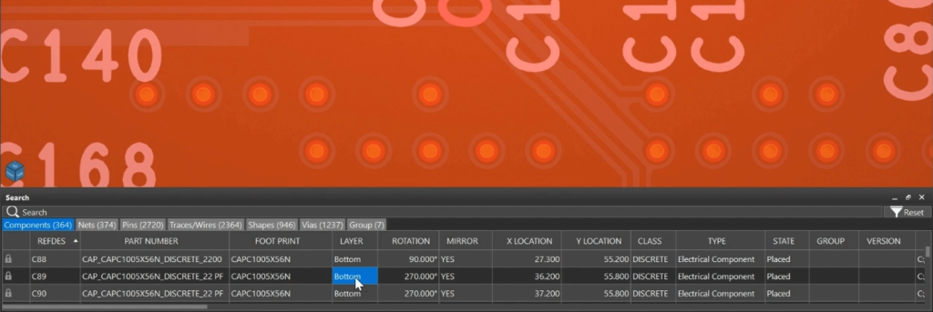
Step 4: View the Search panel. Here all the design information can be easily searched and filtered including:
- Components
- Nets
- Pins
- Traces/Wires
- Shapes
- Vias
- Groups
Note: Double-click a component or layer to highlight it in the 3D view.
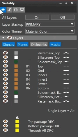
Step 5: Select the Layers mode in the Visibility panel on the left. Here you can configure layer visibility and color.
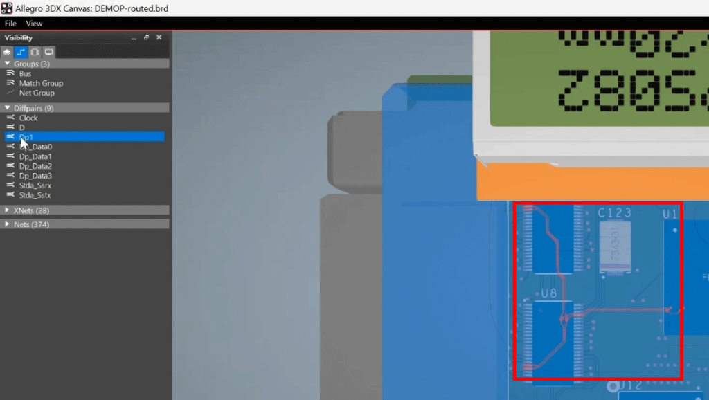
Step 6: Select the Nets mode in the Visibility panel.
Step 7: Expand the Diffpairs category. Double-click an entry to highlight it in the schematic.
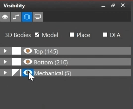
Step 8: Select the Components mode in the Visibility panel. All components are listed, grouped into Top, Bottom, and Mechanical.
Step 9: Select the eye symbol for Mechanical to turn off visibility for the enclosure.
Note: Adjust the view of the board with the middle mouse button. Scroll in and out to zoom, hold the button to pan the view, and hold the button with Shift on the keyboard to rotate the view. Select the white block to the left of the eye for the Top components to make them transparent. Click again to make them opaque.
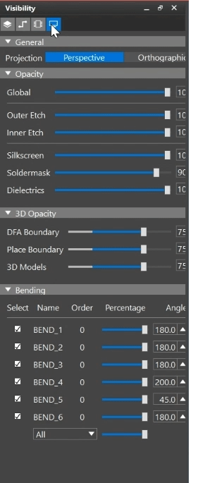
Step 10: Select the Display mode in the Visibility panel. The panel now lists device opacities and bending.
Step 11: Drag the opacity sliders for each layer or 3D object to adjust the opacity.
Viewing Bends in 3D
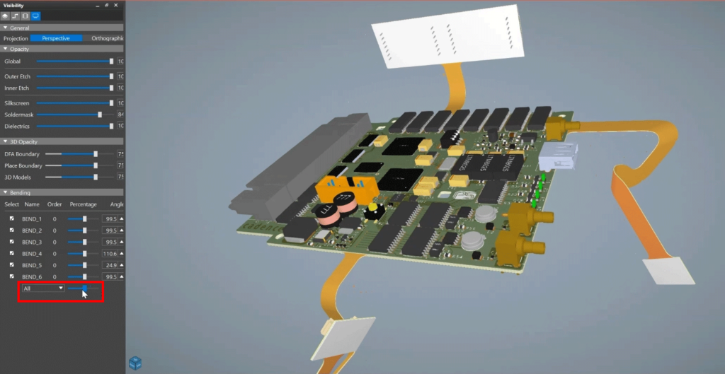
Step 12: Click and drag the slider under Bending for All to adjust all flex bends in the design.
Note: Bends move in real-time and can be adjusted individually or in unison.
Wrap Up & Next Steps
Quickly and thoroughly analyze your PCBs in 3D with the new 3DX canvas in Allegro X. Find out more about the new features in Allegro X here.
