With high pin count components frequently used in today’s complex designs, creating schematic symbols can be tedious, time-consuming, and prone to errors, especially with manual methods for defining pin names and numbers. With EDABuilder, you can use PDF extraction to create component models by automatically extracting pin information from datasheets and validating component data, saving time and reducing errors. EDABuilder allows you to extract pin information in multiple formats including:
- Pin diagrams
- Pin tables
- BGA maps
This quick how-to will provide step-by-step instructions on how to use PDF extraction to create component models from datasheets in EDABuilder.
To follow along, download the provided files above the table of contents.
How-To Video
 Open in New Window
Load a PDF in EDABuilder
Step 1: Open EDABuilder and Select File > New > Symbol from PDF from the menu.
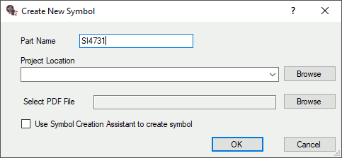
Step 2: The Create New Symbol window opens. Enter SI4731 for the Part Name.
Step 3: Select Browse for the Project Location. Select the working directory and click OK.
Step 4: Select Browse for Select PDF File. Browse to the provided SI4731.pdf file. Select the file and click Open.
Step 5: Click OK to create the project file. The EDABuilder canvas opens to show the loaded PDF.
Use PDF Extraction to Create Component Models: Pin Diagram
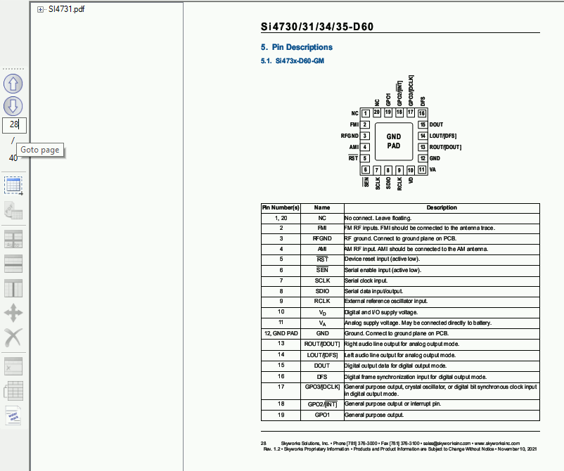
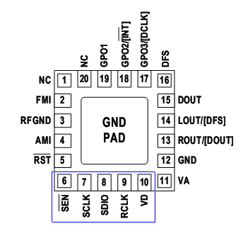
Step 6: EDABuilder can efficiently extract data from pin tables and diagrams to create a new part. Enter 28 into the Page Number text field to navigate to page 28.
Note: Scroll up and down to zoom in and out as needed.
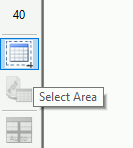
Step 7: The page shows a pin diagram and a pin table. To extract data from the pin diagram, choose the Select Area tool from the sidebar.
Step 8: The Select Area window opens. Select Table/Pin Out Diagram and click OK.
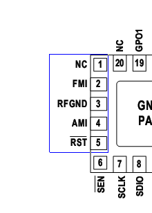
Step 9: Click and drag to select the first group of pins on the left side of the chip, excluding pin 6. Ensure the pin number and pin name are included.
Step 10: The Define Table window opens. Enter 5 for the Number of Rows and 2 for the Number of Columns.
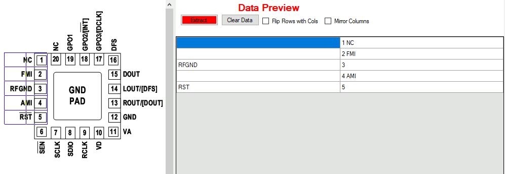
Step 11: Click Generate and Close. The pin names and numbers are listed in the Data Preview panel.
Note: Due to the uneven sizes of each “cell” in the PDF, some of the data in the right column of the generated table should be in the left. Use the Move function to correct this.
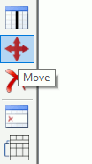
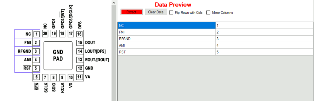
Step 12: Select Move from the sidebar to activate the Move mode.
Step 13: Click and drag the column separator to split the pin names and numbers. The generated table is corrected.
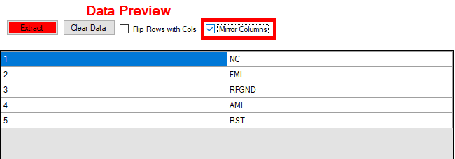
Step 14: For this part, we want to place pin numbers in the left column and names in the right column. To achieve this for this particular selection, check Mirror Columns in the Data Preview panel.
Step 15: Select Extract to copy the selected pins into ScratchPad and clear the preview table for the next set of pins.
Step 16: Choose the Select Area tool from the sidebar. Select Table/Pin Out Diagram and click OK.
Step 17: Click and drag to select the bottom pins 6-10.
Step 18: In the Define Table window, enter 2 for the Row count and 5 for the Column count. Click Generate and Close.
Note: Use the Move mode as needed to adjust the row and column dividers.
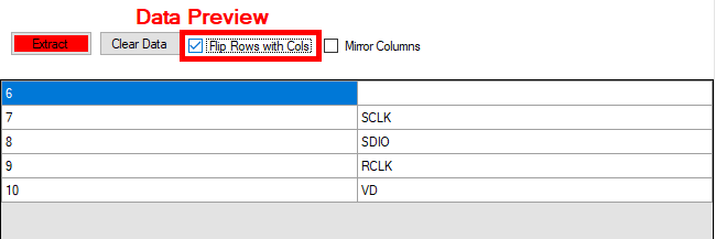
Step 19: The table in the Data Preview panel needs to be transposed to match the convention. Check Flip Rows with Cols to do this.
Step 20: Select Extract to copy the selected pins into ScratchPad.
Step 21: Choose the Select Area tool from the sidebar. Select Table/Pin Out Diagram and click OK.

Step 22: Click and drag to select the right pins 11-15.
Step 23: In the Define Table window, enter 5 for the Row count and 2 for the Column count. Click Generate and Close.
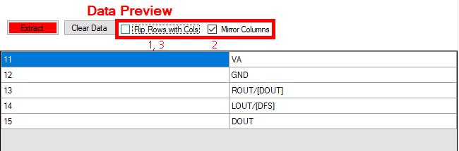
Step 24: View the extracted Data Preview table. The pins are upside-down. To correct this, check Flip Rows with Cols, check Mirror Columns, then uncheck Flip Rows with Cols.
Note: When a component is created, pins can be sorted by name or number, so it is not always necessary to flip an upside-down list of pins at this stage.
Step 25: Select Extract to copy the selected pins into ScratchPad.
Step 26: Choose the Select Area tool from the sidebar. Select Table/Pin Out Diagram and click OK.
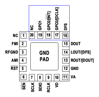
Step 27: Click and drag to select the top pins 16-20.
Step 28: In the Define Table window, enter 2 for the Row count and 5 for the Column count. Click Generate and Close.
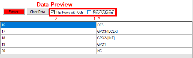
Step 29: In the Data Preview, check Mirror Columns, check Flip Rows with Cols, then uncheck Mirror Columns to properly transpose the data.
Step 30: Select Extract to copy the selected pins into ScratchPad.
Step 31: Select View ScratchPad from the toolbar to view the generated table.
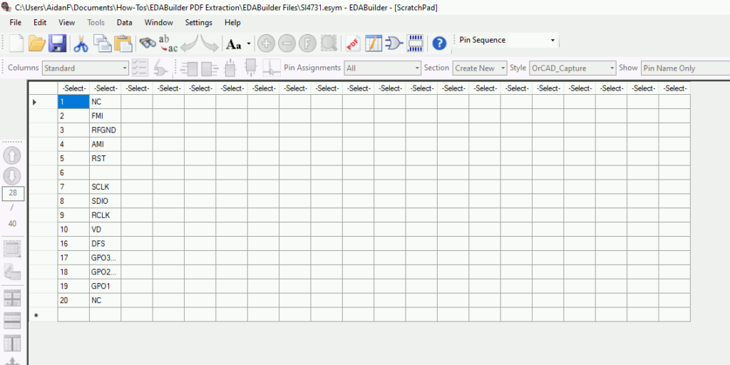
Step 32: View the table in Scratchpad. All pins are listed in the correct order.
Note: To continue with this part data and create the schematic symbol graphic, select the function for each column and copy the table to the Symbol View. For more information on creating a schematic symbol with EDABuilder, see our how-to here.
Step 33: The next section of this how-to will detail how to create a pin table from a table in a PDF. The data in ScratchPad can be discarded. Right-click in the table and select Delete All.
Step 34: Select View PDFExtraction from the toolbar to return to the PDF extraction.
Use PDF Extraction to Create Component Models: Pin Table
Step 35: Creating a pin table from a PDF table can be done with the same tools. Depending on the PDF structure, some tables can be loaded cleanly Choose the Select Area tool from the sidebar. Select Table/Pin Out Diagram and click OK.
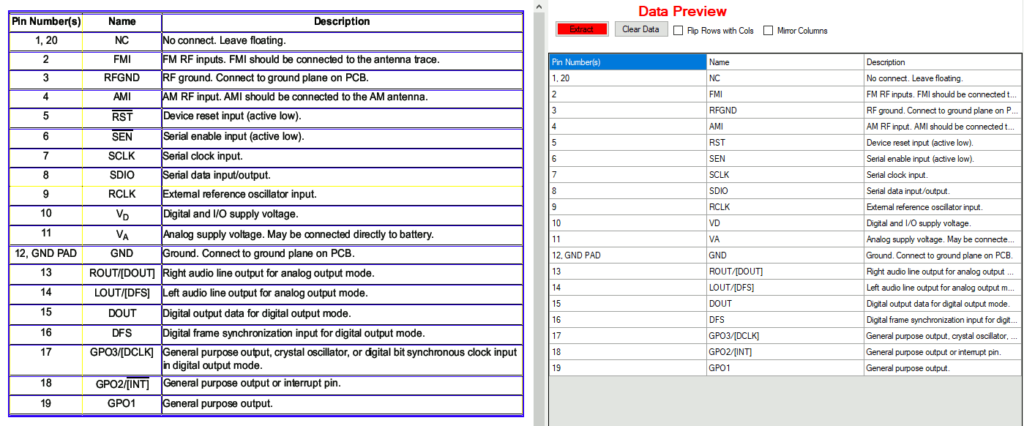
Step 36: Click and drag to select the entire table. Each cell is added to the Data Preview panel as printed.
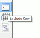
Step 37: The table header does not contain pin information and is not needed. To remove it from the generated table, select Exclude Row from the sidebar.
Note: Alternatively, during data selection exclude the header and begin selection at pin 1.
Step 38: Select the header row. The row is removed from the generated table.
Step 39: Select Extract to copy the data into ScratchPad.
Step 40: Select View ScratchPad from the toolbar. The pins have been extracted and can be viewed in the correct order.
Use PDF Extraction to Create Component Models: Pin Table with Adjustment
Note: Due to the formatting on some component datasheets, sometimes pin information needs to be manipulated once extracted. The following steps will discuss the steps required in this situation.
Step 41: Select File > New > Symbol from PDF from the menu.
Step 42: In the Create New Symbol window, enter CD4051 for the Part Name.
Step 43: Select Browse for the PDF file. Select the provided CD4051.pdf and click Open.
Step 44: Click OK.A prompt appears to save changes to SI4731 before opening a new project. Click Yes to save the changes.
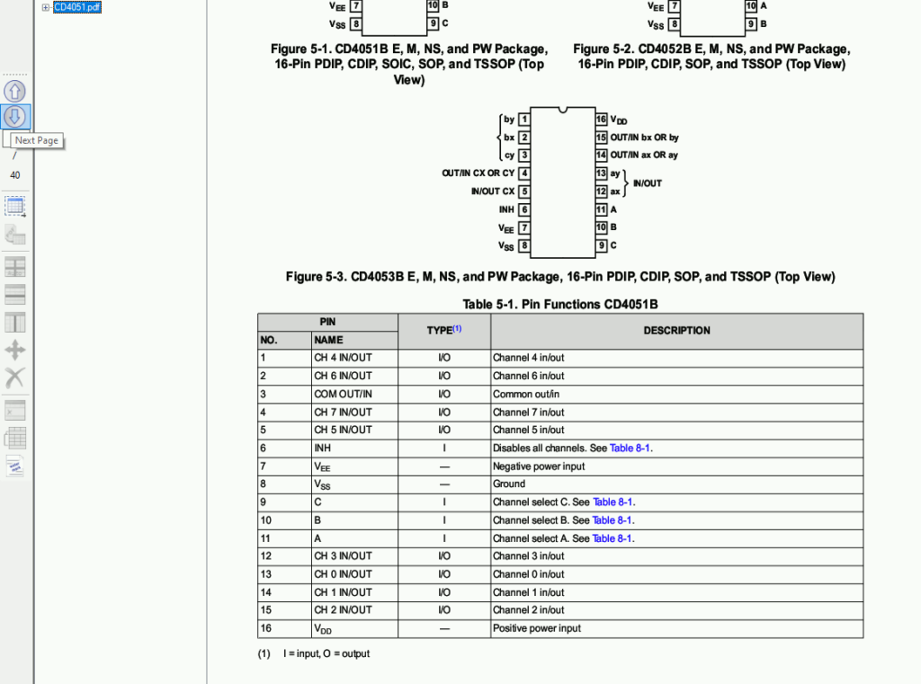
Step 45: CD4051.pdf opens in the EDABuilder window. Select Next Page twice to navigate to the table on page 3.
Step 46: Choose Select Area from the sidebar. Select Table/Pin Out Diagram and click OK.
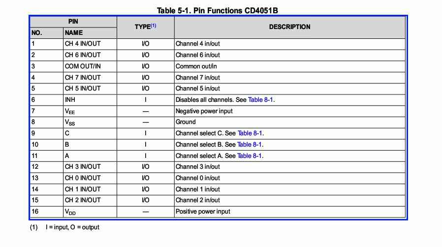
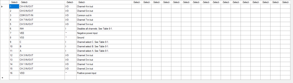
Step 47: Click and drag to select Table 5-1.
Step 48: Because the separators in this table are not visible to EDABuilder, the number of rows and columns must be manually defined. The Define Table window opens. Select Auto Generate Rows and Columns.
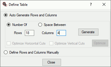
Step 49: Enter 18 for the Row count and 4 for the Column count.
Note: Row count should be determined by the number of vertical cells that would be required to evenly divide the table. In this example, the table can be divided into eighteen rows- one for each pin plus two header rows. Column count should be determined by the number of horizontal cells in each row.
Step 50: Click Generate and Close. A table is generated in the Data Preview panel, but because EDABuilder assumes evenly-spaced columns, the column margins are not in the correct places and the text formatting is incorrect.
Step 51: There are many ways to adjust the column margins. The easiest way is to move the separators. To do this, select Move from the sidebar.
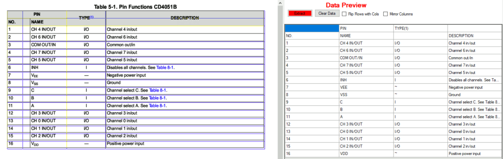
Step 52: Click and drag the column separators in the table. The Data Preview spreadsheet is updated to split the data into the correct columns.
Step 53: To remove the header rows, select Exclude Row from the sidebar and click the header rows.
Step 54: Click Extract in the Data Preview panel to copy the table into ScratchPad.
Step 55: Select View ScratchPad from the toolbar. The pins have been extracted and can be viewed in the correct order.
Wrap Up & Next Steps
Use PDF extraction to copy pin data from a datasheet and quickly create component models with EDABuilder to obtain a realistic representation of the parts used in your schematic designs. To continue with the extracted pin information and quickly create a schematic symbol graphic view this how to and get more step-by-step instructions for EDABuilder at EMA Academy.

