With today’s ever-more-complex designs, it can be time-consuming to accurately model circuit behavior; however, the need to do so is increasingly important. In OrCAD PSpice you can use Analog Behavioral Models (ABMs) to define mathematical expressions to model circuit functionality instead of defining all the required components. With PSpice, you can use analog behavioral models to quickly model:
- Basic Functions (Addition, Subtraction, Gain, Multiplication, etc.)
- Instantaneous Power
- Limiters
- Laplace Transforms
- Chebyshev Filters (Lowpass, Highpass, Bandpass, Bandreject)
- Mathematical Functions (Log, Sin, Square Root, etc.)
- Custom Expressions
This quick how-to will provide step-by-step instructions on how to use analog behavioral models in OrCAD PSpice Designer to incorporate a gain into SPICE simulations.
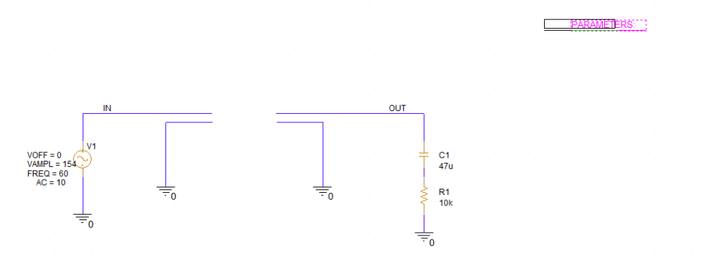
To follow along, download the provided design above the table of contents.
How-To Video
 Open in New Window
Placing a Parameter List
Step 1: Select Place > Component from the menu.
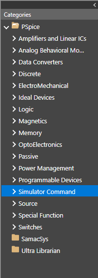
Step 2: In the Unified CIS tab, expand the PSpice category and select Simulator Command.
Step 3: Scroll down and select the part with the name PARAM. Right-click and select Place.
Step 4: Click to place the parameter list in the schematic. Right-click and select End Mode.
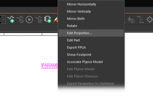
Step 5: Right-click the list and select Edit Properties.
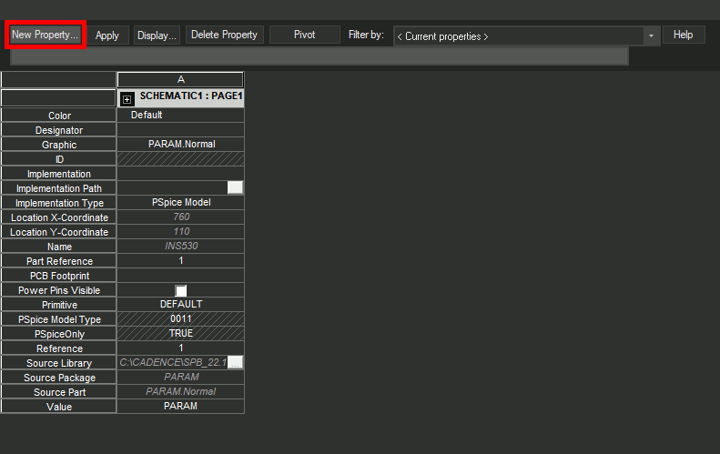
Step 6: In the Property Editor tab, select New Property.
Step 7: Enter GAIN for the property name and 2 for the value.
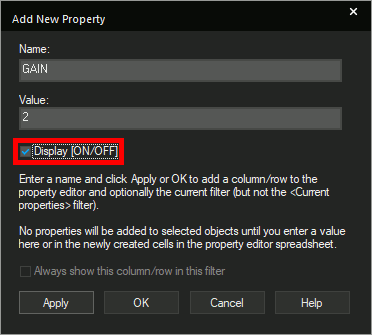
Step 8: Check the option for Display [ON/OFF] to show the property in the schematic. Click OK.
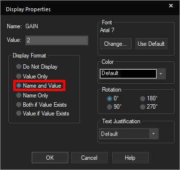
Step 9: In the Display Properties window, select Name and Value under Display Format and click OK.
Note: This will show the name and value of the property on the schematic.
Step 10: Click Apply and close the Property Editor tab.
Placing the Gain ABM
Step 11: Back in the Unified CIS tab, select the PSpice > Analog Behavioral Models folder in the Categories list.
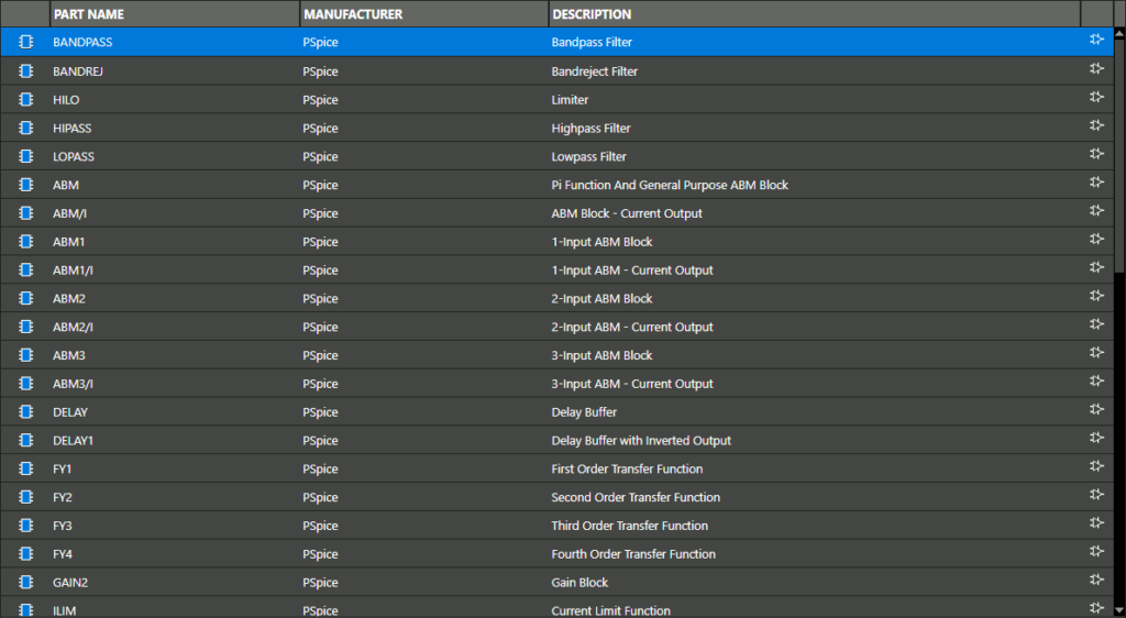
Note: In this folder, you can find basic mathematical blocks, formula-based parts, and frequency-shaping parts such as filters. You will also find complex mathematical blocks that will allow you to implement Laplace transforms, differentiate, integrate, and more.

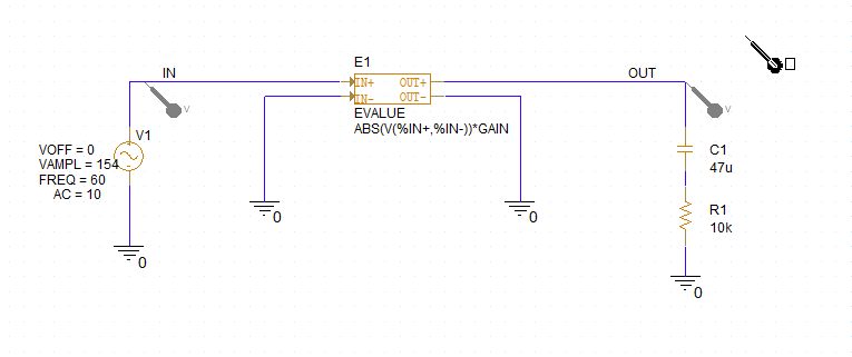
Step 12: Select the PSpice folder. Enter EVALUE into the search field and press Enter.
Step 13: Right-click the EVALUE part and select Place.
Step 14: Click to place the part in the empty space in the schematic. Right-click and select End Mode.
Note: The EVALUE block can be used to assign a mathematical expression as a voltage output.
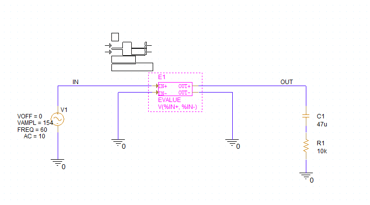
Step 15: Double-click the predefined expression V(%IN+, %IN-) to change it.
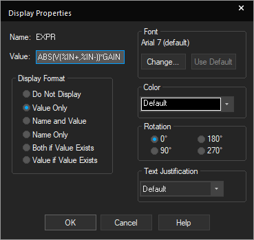
Step 16: Enter the expression ABS(V(%IN+,%IN-))*GAIN and click OK.
Note: This expression can contain global parameters and net names that aren’t connected to the ABM, including the global parameter GAIN. Use the percent sign % to specify a pin on the ABM.
Creating a Simulation Profile
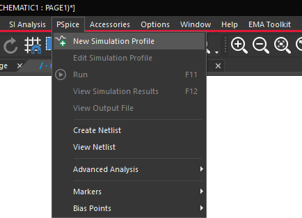
Step 17: Select PSpice > New Simulation Profile from the menu.
Step 18: Name the profile TRANS and click Create.
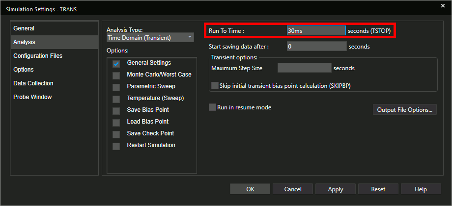
Step 19: The Simulation Settings window opens. Set the Run To Time to 30ms. Leave the other settings as the defaults and click OK.
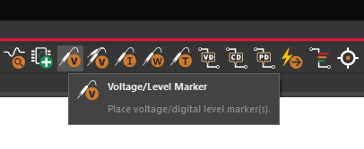
Step 20: Select the Voltage/Level Marker button from the toolbar.
Step 21: Click to place probes at the input and output of the circuit. Right-click and select End Mode.
Running the Simulation
Step 22: Select PSpice > Run from the menu.
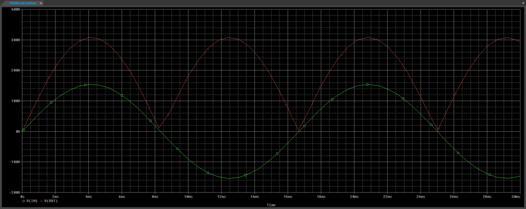
Step 23: View the simulation results. The output is a rectified sine wave with twice the peak voltage of the input, as defined in the expression.
Wrap Up and Next Steps
Use Analog Behavioral Models to quickly define circuit functionality using mathematical expressions and accelerate your SPICE simulations with OrCAD PSpice. To learn more about PSpice and using ABMs in SPICE simulation, view our free PSpice Walk-through series as well as other PSpice courses at EMA Academy. Test out this feature and more with a free trial of OrCAD.

