With design complexity increasing and the continued desire for smaller, sleeker products, it’s crucial to verify a realistic representation of the PCB in 3D. The seamless, powerful 3D engine in OrCAD X lets you efficiently use 3D functionality to design, review, and verify your PCB design in 3D to produce a successful end product.
This quick how-to will provide step-by-step instructions on how to use 3D functionality in OrCAD X Presto.
To follow along, download the provided files above the table of contents.
How-to Video
 Open in New Window
Activating 3D Functionality
Step 1: Open the provided design, presto_tutorial3D.brd, in OrCAD X Presto.
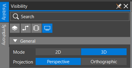
Step 2: Select Visibility to open the Visibility panel.
Step 3: Select the button for the Display mode.
Step 4: Select 3D for the Mode to open the 3D viewer.
Step 5: View the board in 3D.
Configuring 3D Visibility
Step 6: If the Visibility Panel is not opened, select the Visibility tab to open the Visibility panel again. Here you can configure 3D visibility options.
Step 7: Select the Component button to configure visibility options for the components on the PCB.
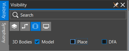
Step 8: Click to uncheck Place to remove placement guides and view the 3D models.
Step 9: Click the arrow next to Top to expand Top and view all the components placed on the top of the PCB. Here you can turn on and off visibility for individual components on the PCB and all components on the PCB.
Note: 3D models for components must be mapped to the PCB footprint using the footprint editor.
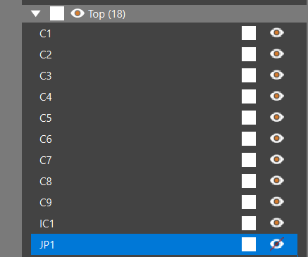
Step 10: Click to select the Eye icon for JP1 to turn off visibility. Select the Eye icon again to turn visibility on.
Note: Click the eye icon at the Top level to control visibility for all components placed on the top of the PCB.
Step 11: Click the arrow next to Top to contract the Top category.
Mapping an Enclosure
Step 12: Click the arrow next to Mechanical to expand the Mechanical category.
Step 13: Select the plus sign to add a new mechanical model.
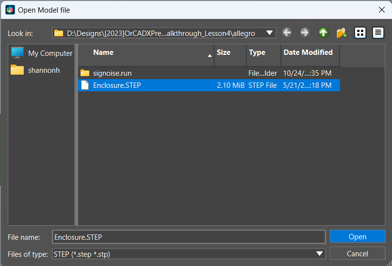
Step 14: Browse to the location of the provided 3D model and select Enclosure.STEP. Click Open.
Step 15: Click to select the enclosure in the PCB canvas to open the properties panel.
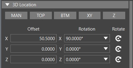
Step 16: In the Properties panel, under 3D Location, enter 50.5 for the X Offset. Select Enter or Tab on the keyboard.
Step 17: Enter 90 for the X Rotation or select the Rotate icon once to rotate 90-degrees around the X-axis.
Step 17: Complete the enclosure mapping by entering the following parameters:
- Y Offset: 25
- Z Offset: 4
Note: Adjusting the rotation will change the values of the offset. There are multiple methods to adjust the model mapping including:
- MAN: Manually drag the 3D model into the correct location.
- TOP: Snap a single face from the 3D model to the top of the PCB surface.
- BTM: Snap a single face from the 3D model to the bottom of the PCB surface.
- XY: Align a number of elements from both the 3D model and the footprint or PCB in the XY plane.
- Z: Align one or more faces from the 3D model and the footprint or PCB in the Z direction.
- X, Y, and Z Offset and Rotation: Manually enter values for the offset and rotation in the X, Y, and/or Z directions.
For more information on mapping a 3D model in OrCAD X Presto, see our how-to here.
Step 18: View the mapped enclosure.
Use 3D Functionality in OrCAD X
Step 19: Select the Visibility tab. Next to Enclosure, select the checker pattern icon to make the model opaque.
Step 20: Select the Eye icon to hide the enclosure.
Step 21: Select the Display icon.
Step 22: Under Opacity, click and drag the slider for Global to adjust the opacity of all objects in the 3D view. These can be adjusted individually as well.
Note: 3D Opacity can also be configured for DFA Boundary, Place Boundary, and 3D Models.
Step 23: Select the Visibility tab to close the panel or click to select a blank location in the PCB canvas.
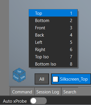
Step 24: Click to select the cube in the bottom left corner of the PCB canvas. Here you can select from pre-defined views to analyze the PCB in 3D.
Step 25: Select Top.
Note: The 3D view can be rotated by holding the middle mouse button and SHIFT while moving the mouse.
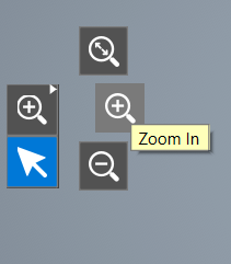
Step 26: Right-click on the Zoom Fit icon and select Zoom In.
Using the Search Panel in 3D Mode
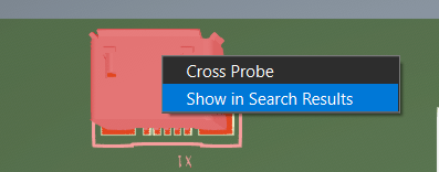
Step 27: Right-click on the USB component, X1, and select Show in Search Results.
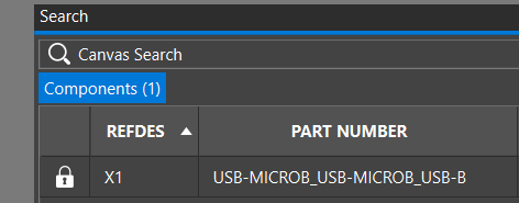
Step 28: Review the information and select the lock icon to lock the component in place and prevent undesired movement.
Step 29: Close the Search panel.
Measuring in 3D in OrCAD X
Step 30: Click to select IC1.
Step 31: Hold ALT on the keyboard and hover over JP2 to measure the distance between the two components. Release ALT when finished.
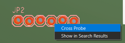
Step 32: Right-click JP2 and select Cross Probe.
Step 33: Select Visibility to open the Visibility panel then select 2D for the Mode.
Step 34: Select Visibility again to close the Visibility panel and view the PCB. JP2 is highlighted for easy identification.
Step 35: Select the Visibility tab and choose 3D for the mode.
Step 36: Select the Component tab. Click the Eye icon to turn visibility on for the Enclosure and click the Transparency icon to make the enclosure transparent.
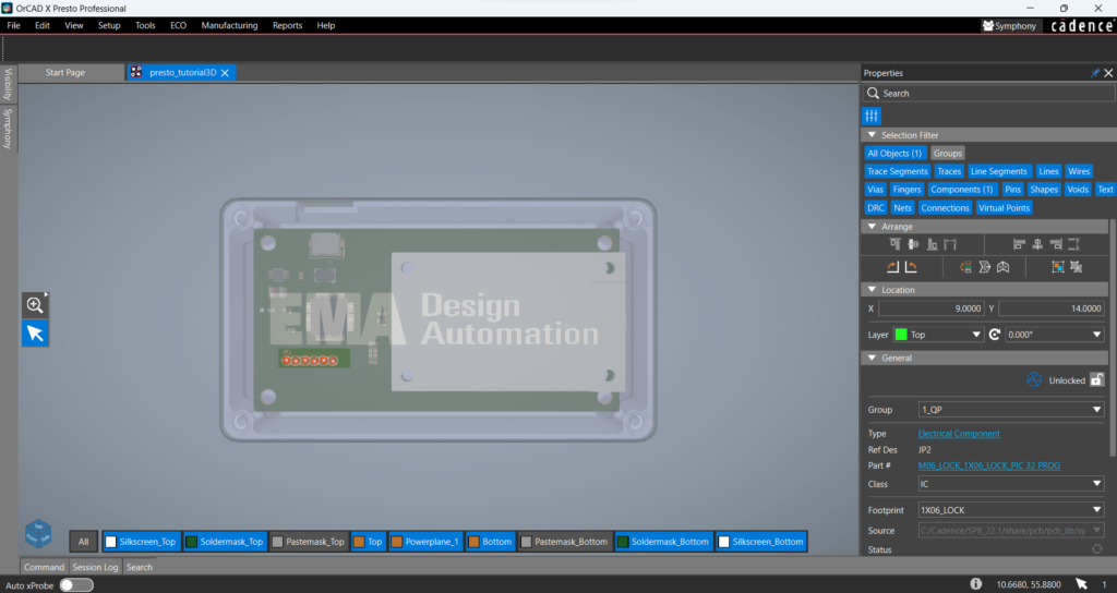
Step 37: In the properties panel with JP2 still selected, enter 9 for the X location. Press Enter on the keyboard.
Step 38: Enter 14 for the Y Location and press Enter on the keyboard.
Step 39: View the integration between the Enclosure and 3D PCB.
Note: Collision checking can be performed by configuring 3D clearance rules and performing design rule checks.
Wrap Up & Next Steps
Use 3D functionality in OrCAD X to analyze and complete your PCB designs efficiently. Test out these features and more with your free trial of OrCAD X. Get additional step-by-step instructions for OrCAD X Presto, walk-through courses and more at EMA Academy.
