Throughout the electronic design process, it’s common for components or connections to change making it crucial to keep all parts of a design up to date to prevent errors in the finished product. Establishing bidirectional communication between the schematic and PCB layout will ensure data such as reference designators, design rules, components, and connections are accurate. OrCAD Capture makes it easy to sync the schematic and PCB providing a detailed list of any changes with the Design Sync feature.
This quick how-to will provide step-by-step instructions on how to sync the schematic and PCB in OrCAD Capture with Design Sync.
To follow along, download the provided files above the table of contents.
How-To Video
 Open in New Window
Making a Change to the Schematic
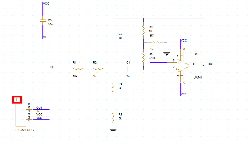
Step 1: Open the provided design in OrCAD Capture.
Step 2: Right-click resistor R4 and select Copy.
Step 3: Right-click and select Paste or press CTRL-V on the keyboard.
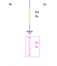
Step 4: Click to paste the resistor directly under the R4 ground.
Step 5: Hold Alt on the keyboard and click and drag the ground to disconnect it from R4.
Note: Holding Alt while moving a component will prevent any wires attached to the component from moving with it.
Step 6: Click and drag the wire stub at the end of R4 to connect it to the new resistor.
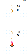
Step 7: Select Place > Wire from the menu, the Wire button from the toolbar, or press W on the keyboard. Connect the new resistor to ground. Press Escape on the keyboard when finished.
Sync the Schematic and PCB
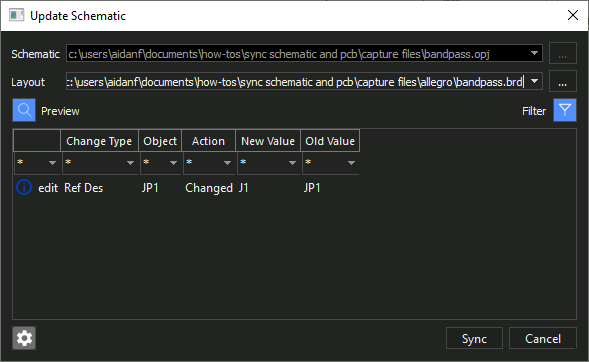
Step 8: To push the new resistor and connections to the PCB, select PCB > Update Layout from the menu.
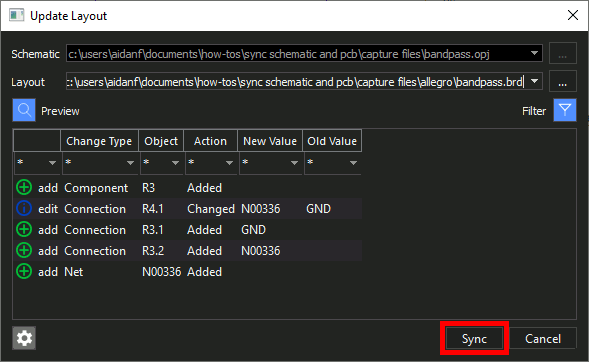
Step 9: The Update Layout window opens, showing the changes made to the PCB layout. R3 and its connections have been added. Click Sync to accept the changes and open PCB Designer.
Step 10: The Product Choices window opens. Select the appropriate license and click OK.
Updating the PCB Layout
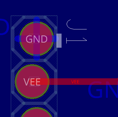
Step 11: PCB Designer opens to the board as it was before the change. To add the new component, select Place > Components Manually from the menu.
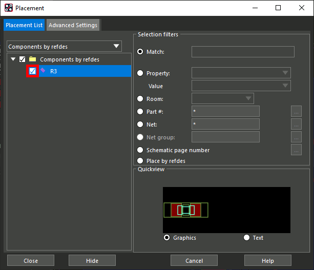
Step 12: The Placement window opens, showing R3 in the component list. Check R3 to place it.
Step 13: Click Hide in the Placement window to hide it for better visibility.
Note: Do not close the Placement window. This will cancel the placement command.
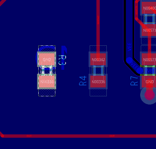
Step 14: Click to place the part in the board canvas. Right-click and select Done when finished.
Step 15: To connect the resistor to ground, select Route > Create Fanout from the menu.
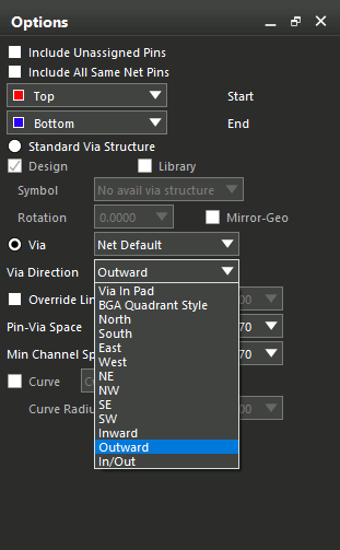
Step 16: In the Options panel, set the Via Direction to Outward.
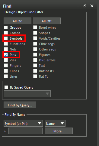
Step 17: Check Pins in the Find filter panel. Ensure Symbols is unchecked.
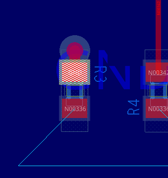
Step 18: Click the ground pin on R3 to create the fanout.
Step 19: To connect the other pin of R3, select Route > Connect from the menu.
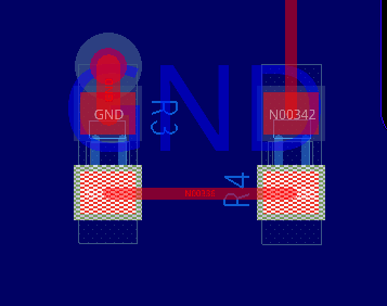
Step 20: Click the unconnected pin of R3 to start routing, then click the unconnected pin of R4 to finish. Right-click and select Done.
Making a Change to the PCB
Note: Changes to the PCB can be synced to the schematic as well.
Step 21: Select Edit > Text from the menu.
Step 22: Select the reference designator for JP1 to change it.
Step 23: Change the reference designator to J1 and press Enter. Right-click and select Done.
Step 24: Select File > Save from the menu. If prompted to overwrite the PCB file, click Yes.
Syncing the Changes to the Schematic
Step 25: Return to OrCAD Capture and select PCB > Update Schematic from the menu.
Step 26: The Update Schematic window opens, showing the reference designator change. Click Sync to change the schematic.
Step 27: View the schematic. The reference designator for JP1 has changed to J1.
Wrap Up & Next Steps
Quickly sync the schematic and PCB to keep your entire design up to date with bi-directional integration between OrCAD Capture and OrCAD PCB Designer.
Test out this feature and more with a free trial of OrCAD.
Want to learn more about Capture? Get access to free how-tos, courses, and walk-throughs at EMA Academy.

