Determining the optimal values for components in a design can be a tedious and time-consuming process. While it’s easy to sweep the value of a single component, this may be required for several components in your design which lengthens the time spent on simulation and may push the project off schedule. With PSpice Designer Plus, quickly sweep multiple parameters simultaneously to ensure you select the ideal component values and other operating parameters with the Parametric Plotter.
This quick how-to will provide step-by-step instructions on how to sweep multiple parameters in a single simulation with the parametric plotter in PSpice Designer Plus.
To follow along, download the provided files above the table of contents.
How-To Video
[coming soon]
Creating the Parameter List
Step 1: Open the provided design in PSpice Designer Plus.
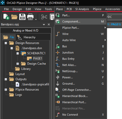
Step 2: A global parameter list can be placed in the design to easily create and access design parameters. To place a list, select Place > Component from the menu.
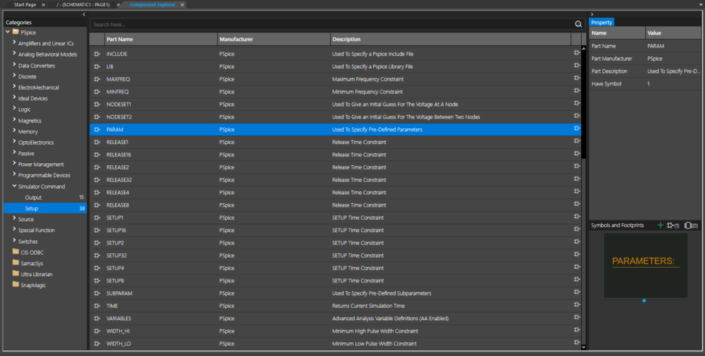
Step 3: The Component Explorer tab opens. From here, you can place pre-defined PSpice components as well as schematic symbols from Ultra Librarian, SamacSys, and your personal library. Expand the PSpice Folder and select Simulator Command > Setup.
Step 4: Select PARAM from the component list. Double-click to attach the part to your cursor.
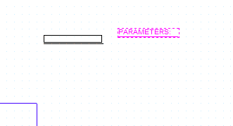
Step 5: Click to place the parameter list in the schematic, then right-click and select End Mode.
Defining the Parameters
Step 6: Double-click the parameter list to open the Property Editor tab.
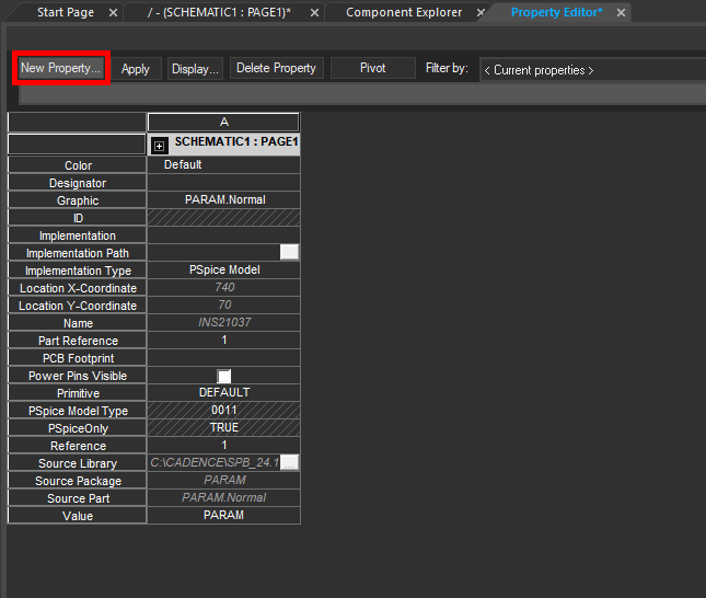
Step 7: The Property Editor tab opens, showing a list of properties for the selected component. Global parameters for a PARAM list are defined here. To define a parameter, select New Property.
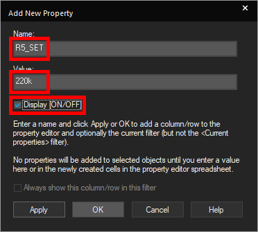
Step 8: The Add New Property window opens. Enter R5_SET for the property name and 220k for the value.
Step 9: Check the option for Display [On/Off] to show the property on the parameter list object. Click OK.
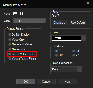
Step 10: The Display Properties window opens. Here you can configure how to display the property in the parameter list. Select Both if Value Exists and click OK.
Step 11: Select New Property to add a new parameter.
Step 12: Name the new property R7_SET and enter 1k for the value. Check Display [On/Off] and click OK.
Step 13: Select Both if Value Exists in the Display Properties window and click OK.
Step 14: Click Apply and close the Property Editor tab.
Changing Component Values
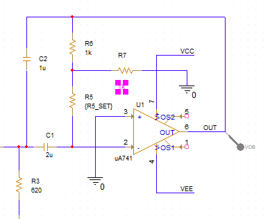
Step 15: Global design parameters can be assigned to component values with the following steps. Double-click the value of R5 to change it.
Step 16: Enter {R5_SET} for the value and click OK.
Note: Curly brackets for a component property value indicate a variable parameter.
Step 17: Double-click the value of R7 to change it.
Step 18: Enter {R7_SET} for the value and click OK.
Running the Simulation
Step 19: A transient, AC sweep, or DC sweep simulation must be run before a parametric sweep can be performed. Select PSpice > Run from the menu to start the simulation.
Note: The simulation is pre-defined in this example. To learn how to configure and run a new simulation in PSpice, see our how-to here.
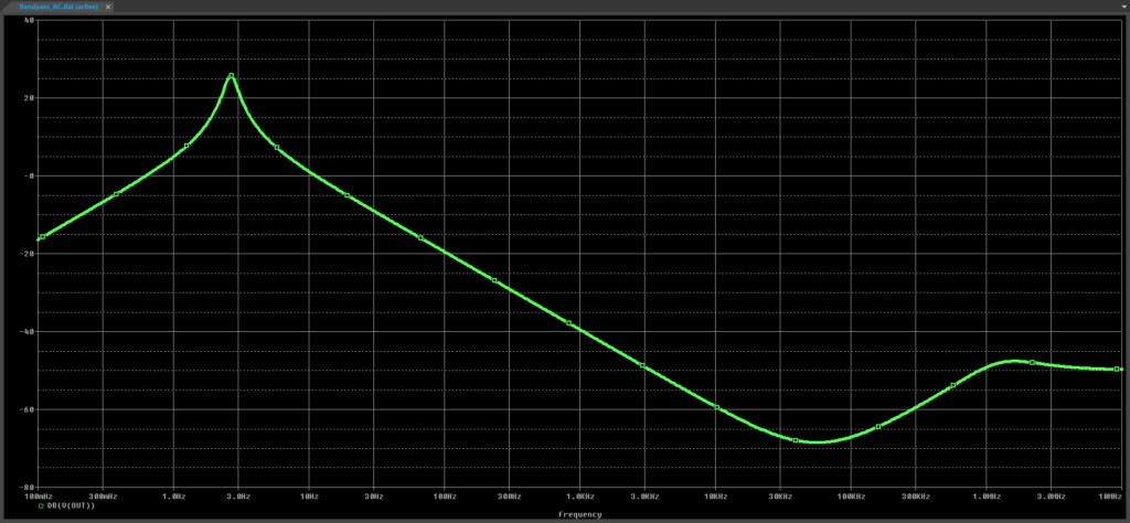
Step 20: View the AC sweep results. The output amplitude peaks at a low frequency.
Defining a Measurement Result
Step 21: Parametric sweeps are based on numerical measurement results. To activate numerical measurements, select View > Measurement Results from the menu.
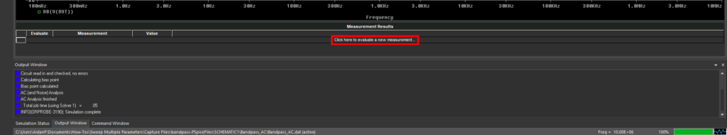
Step 22: The Measurement Results subpanel opens at the bottom of the plot. Select Click Here to Evaluate a New Measurement to create a new measurement.
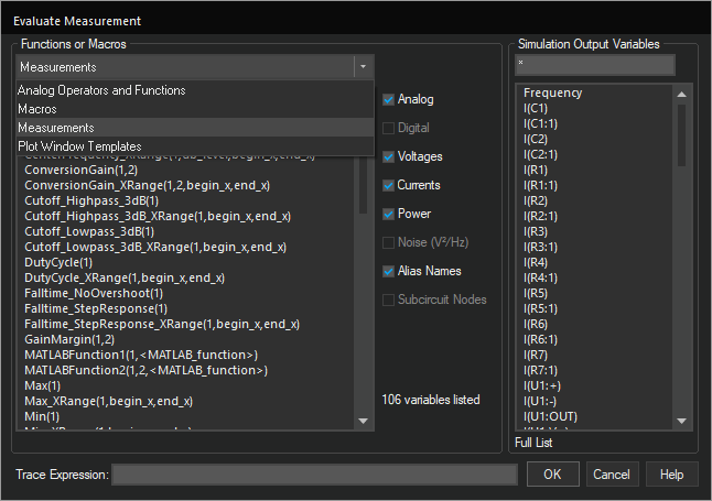
Step 23: The Evaluate Measurement window opens. Here you can define the measurement to add from a list of functions and parameters or via the Trace Expression text field.
Select Measurements from the Functions or Macros dropdown.
Step 24: Select Max(1) from the Measurements list.
Step 25: A Maximum function is added to the Trace Expression field. Select V(OUT) from the Simulation Output Variables list to define the output variable.
Step 26: Type a forward slash within the Max() function to indicate division.
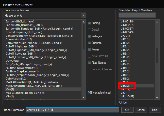
Step 27: From the Simulation Output Variables list, select V(R7:2) to add it to the expression.
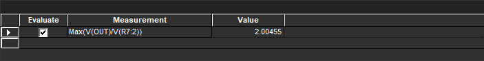
Step 28: Click OK to save the measurement and close the window. The measurement and its value are added to the result list.
Sweep Multiple Parameters: Defining a Sweep
Step 29: With a measurement defined, the Parametric Plotter can be activated. Minimize the PSpice A/D window and select PSpice > Advanced Analysis > Parametric Plot from the menu.
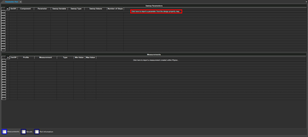
Step 30: Select Click Here to Import a Parameter from the Design Property Map to load in a parameter.
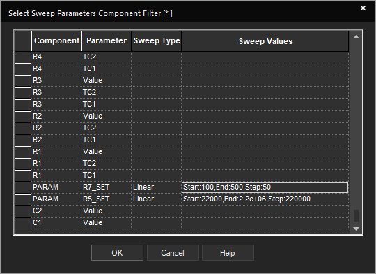
Step 31: The Select Sweep Parameters window opens. Scroll down and select the cell under Sweep Values for parameter R5_SET.
Step 32: The Sweep Settings window opens. Select Linear from the Sweep Type dropdown.
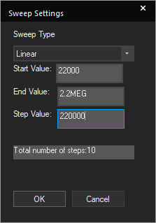
Step 33: A new set of text fields opens to define sweep values. Select 22000 for the start value, 2.2MEG for the End Value, and 220000 for the step value.
Note: The number of steps is automatically filled in. In this case, there are ten steps.
Step 34: Click OK. The sweep is added to the list as an entry.
Step 35: Select the cell under Sweep Values for parameter R7_SET.
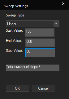
Step 36: In the Sweep Settings window, select Linear for the Sweep Type. Enter 100 for the Start Value, 500 for the End Value, and 50 for the Step Value.
Note: This sweep should have a total of nine steps.
Step 37: Click OK to add the sweep to the list.
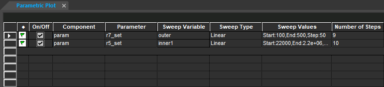
Step 38: Click OK again to save and close the Select Sweep Parameters window. The sweeps are added to the Sweep Parameters subpanel.
Sweep Multiple Parameters: Defining a Sweep Measurement
Step 39: The parameter to measure must be defined as well. Select Click Here to Import a Measurement Created within PSpice in the Measurements subpanel.
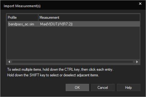
Step 40: The Import Measurements window opens. Select the measurement created earlier and click OK.
Sweep Multiple Parameters: Running the Simulation
Step 41: With the parameters to sweep and the measurement defined, the parametric sweep can be run. Select Run > Start Parametric Plot from the menu.
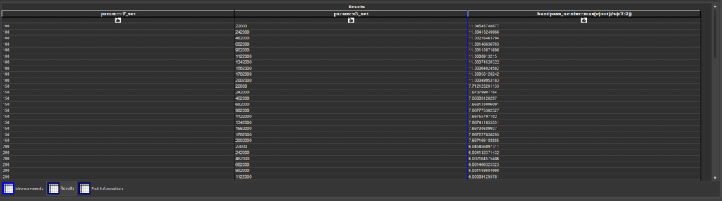
Step 42: The Results tab is selected automatically. All results are shown in the Results subpanel. Observe the effect of varying the values of R5 and R7. Adjusting the value of R7 will have a much more dramatic effect on the measured voltage.
Sweep Multiple Parameters: Creating a Graphical Plot
Step 43: To visualize the parameter table, a graphical plot can be created of the data. Select the Plot Information tab at the bottom of the Results window.
Step 44: Select Click Here to Add Plot in the Plot Information subpanel.
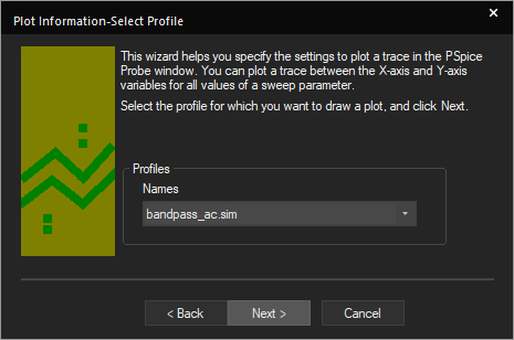
Step 45: The Plot Information wizard opens. First, the simulation must be defined. Select the bandpass_ac.sim simulation from the Profiles dropdown. Click Next.
Step 46: The next step is to define the X Axis variable. Select param:r5_set from the dropdown and click Next.
Step 47: The Y Axis variable must be defined. Select bandpass_ac.sim:max(v(vout)/vr(r7:2)) from the dropdown and click Next.
Step 48: Lastly, the varying parameter must be defined. Select param:r7_set from the dropdown and click Finish.
Note: The parameters defined in the X and Y axes will be plotted multiple times with this parameter varied.
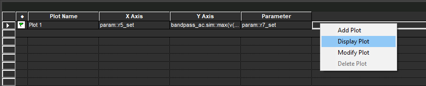
Step 49: The plot is added to the Plot Information subpanel. Right-click and select Display Plot.
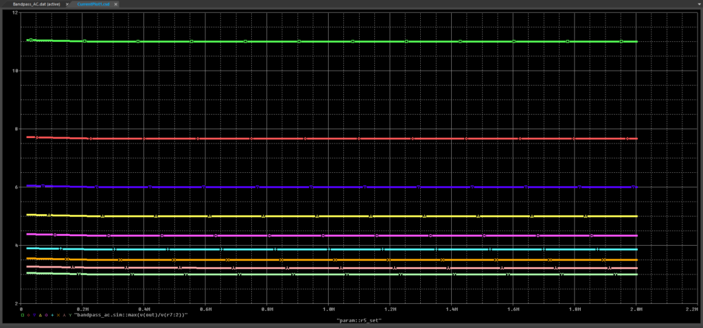
Step 50: The plot opens in the PSpice A/D window. The values of R7 are shown as different color traces.
Wrap Up & Next Steps
Quickly determine optimal component values and design operating conditions with the Parametric Plotter to sweep multiple parameters in PSpice Designer Plus. Test out this feature and more with a free trial of OrCAD. Want to learn more about the Parametric Plotter and the other advanced analysis options in PSpice? View the Level 1 and Level 2 PSpice Advanced Analysis workshops.
