Simulating a circuit prior to production is a crucial step in the design process and can eliminate the need to make test boards earlier in the design process, saving time and resources. However, simulations are often run in ideal conditions which can result in inaccurate real-world results and undesired operation of certain components in the field. New in PSpice 23.1 is the ability to simulate Repeated Exponential Electrical Fast Transients (EFTs). In real-world environments, EFTs are typically caused by events such as switching inductive loads, relay contacts bouncing, or lightning strikes that can introduce high-frequency noise into electrical systems. Simulating EFTs will analyze the robustness and reliability of your design when it is subjected to electrical noise, disturbances, or electromagnetic interference (EMI) and help you:
- Determine how your system will perform in harsh environments
- Prevent data corruption
- Comply with regulatory standards
- Identify and replace vulnerable components
- Optimize circuit design
- Ensure long-term system reliability
- Simulate and test protection circuitry
- Reduce field failures
This quick how-to will provide step-by-step instructions on how to simulate repeated exponential electrical fast transients in PSpice Designer.
To follow along, download the provided files above the table of contents.
How-To Video
 Open in New Window
Placing an Exponential Source
Note: To simulate Repeated Exponential Fast Transient sources a series of pulses is created at a certain interval, then held, then repeated after a longer period. For this example, we will create an exponential source that creates 20 pulses 20usec apart every 1msec.
Step 1: Open the provided design in PSpice Designer 24.1.
Step 2: Select Place > Component from the menu.
Note: If you are using PSpice 23.1, select Place > Part from the menu. Select Add Library under Libraries. Select Source.olb and click Open to open a new parts list. Select VEXP_B and click Place Part.
Step 3: With PSpice selected as the category, enter VEXP_B in the search bar and press Enter.
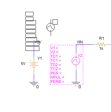
Step 4: Double-click the VEXP_B component. Click to place the exponential source in the empty space in the schematic. Right-click and select End Mode.
Defining Exponential Parameters
Step 5: Right-click the source and select Edit Properties. The Property Editor tab opens.
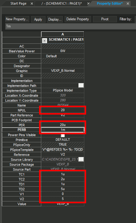
Step 6: Select the cell for V1, the Minimum Voltage Level. Enter 0.
Step 7: Define the following values for the following cells:
- Maximum Voltage Level, V2: 5
- Rise Time Constant, TC1: 1u
- Fall Time Constant, TC2: 2u
- Rise Delay, TD1: 1u
- Fall Delay, TD2: 5u
Step 8: Select the cell for Pulse Period (PER) and enter 20u. This will repeat the pulse every 20 microseconds.
Step 9: Select the cell for Number of Pulses (NPUL) and enter 20. This will repeat the pulse 20 times in a single long cycle.
Step 10: Select the cell for Repeat Burst Period (PERB) and enter 1m. This will send 20 pulses, 20usec apart, every 1msec.
Step 11: Click Apply and close the Property Editor tab.
Simulate Repeated Exponential Electrical Fast Transients (EFTs)
Step 12: Select PSpice > New Simulation Profile from the menu.
Step 13: Enter EFT_TRANS for the name and click Create.
Note: If the Product Choices window opens, select the appropriate license and click OK.
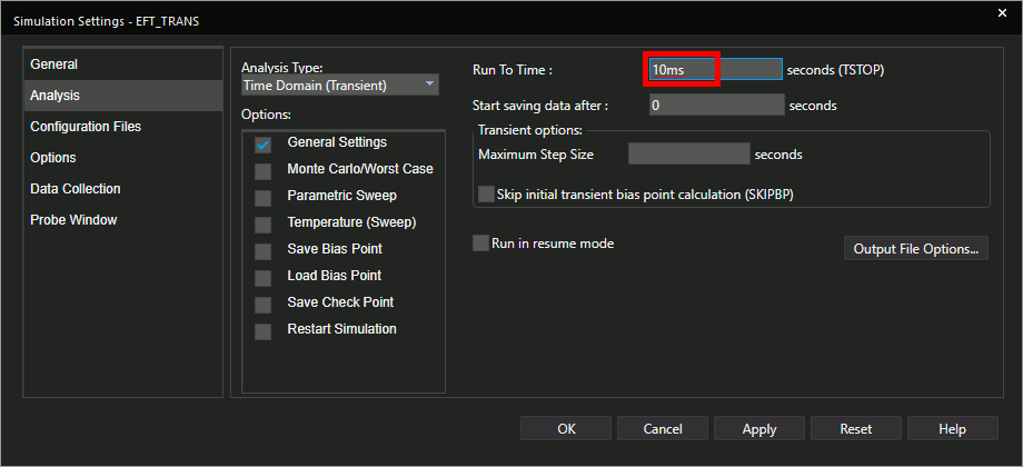
Step 14: Set the Run To Time to 10ms.
Step 15: Leave the other settings as the defaults and click OK.
Step 16: Select the Voltage/Level Marker button from the toolbar.
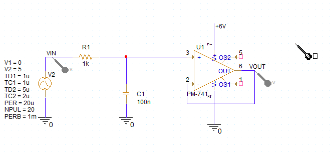
Step 17: Click to place probes at the VIN and VOUT nets. Right-click and select End Mode.
Step 18: Select PSpice > Run from the menu.
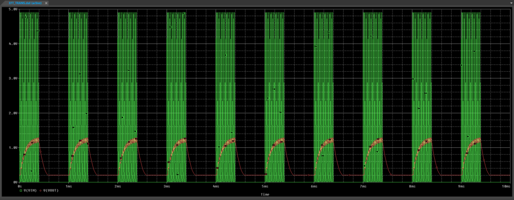
Step 19: View the results. The exponential pulses and the filter’s response to them are shown.
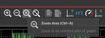
Step 20: To get a closer look at the exponential pulses, select Zoom Area from the toolbar.
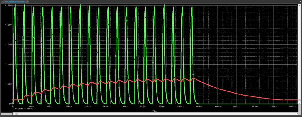
Step 21: Click and drag to select one of the pulse periods. Release the mouse to zoom in. The exponential rise and decay is clearly visible.
Wrap Up & Next Steps
Simulate repeated Exponential Electrical Fast Transients (EFTs) in PSpice Designer to ensure the reliability and robustness of your PCB designs. Upgrade to the latest 23.1 release or test out this feature and more with a free trial of OrCAD.