Circuit simulations are often performed with ideal conditions; however, circuits experience noise in the field that can affect behavior and functionality. Simulating realistic noise by combining and configuring additional sources into a circuit can be a challenging and time-consuming. Easily incorporate noise into simulations and analyze realistic circuit behavior with configurable noise sources and randomization functions with OrCAD PSpice.
This how-to will provide step-by-step instructions for three different methods to simulate noise including:
- Random noise source
- Randomization functions for Transient and DC Analysis (RNDR)
- Randomization functions for sweeps (RNDC)
To follow along, download the provided files above the table of contents.
How-To Video

Using Noise Sources
A Noise Source combines a source with a random noise model. This will produce random values within a certain range at every solved time point to simulate real-world transient noise. Utilizing a voltage or current noise source in OrCAD PSpice is the quickest way to incorporate random noise.
Step 1: Open OrCAD PSpice.
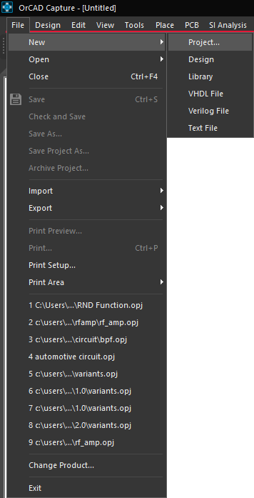
Step 2: Select File > New > Project.
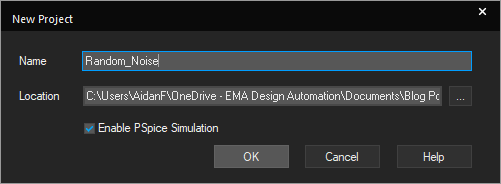
Step 3: Name the file Random_Noise and select a location to save the project. Make sure Enable PSpice Simulation is checked and click OK.
Step 4: Select Create a blank project and click OK.
Creating a Circuit in PSpice
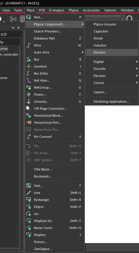
Step 5: Select Place > PSpice Component > Resistor from the menu.
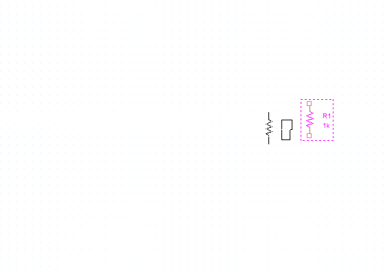
Step 6: Click to place the component. Use R on the keyboard to rotate as needed.
Step 7: Select Place > PSpice Component > PSpice Ground from the menu.
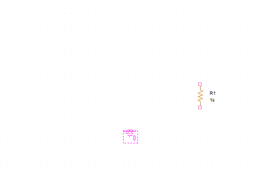
Step 8: Click to place the ground at the bottom of the circuit. Right-click and select End Mode.
Creating a Noise Source
Step 9: Select Place > PSpice Component > Modeling Application from the menu.
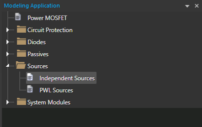
Step 10: From the Modeling Application, select Sources > Independent Sources.
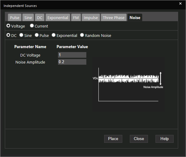
Step 11: Select the Noise tab.
Note: Noise can be incorporated for DC, Sine, Pulse, Exponential, and Random Noise.
Step 12: Set DC Voltage to 1 and Noise Amplitude to 0.2. Select Place.
Note: The Noise Amplitude is the difference between the maximum voltage limit and the minimum voltage limit. In this example, the voltage will be varied from 0.9V to 1.1V.
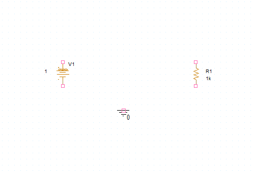
Step 13: Click to place the source on the schematic. Close out of the Modeling Application.
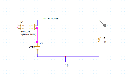
Completing the Schematic
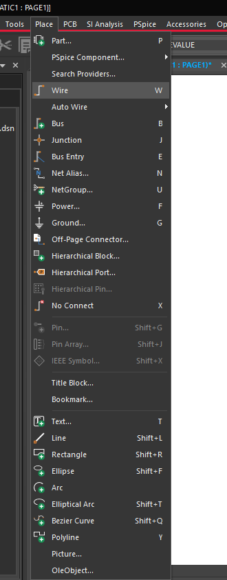
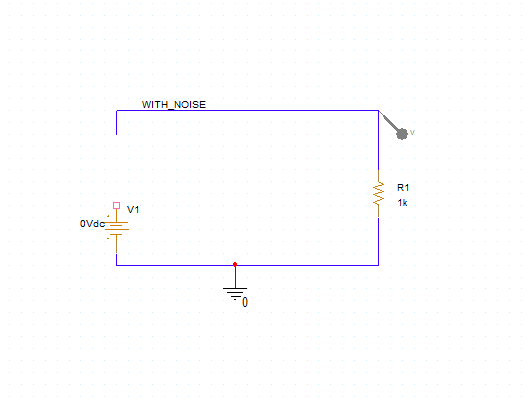
Step 14: Select Place > Wire from the menu, the Wire button on the toolbar, or press W on the keyboard.
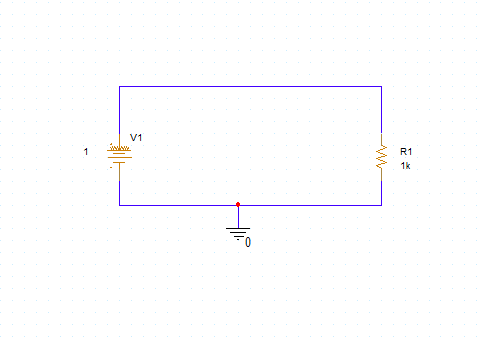
Step 15: Wire the schematic as shown above. Press Escape on the keyboard when finished.
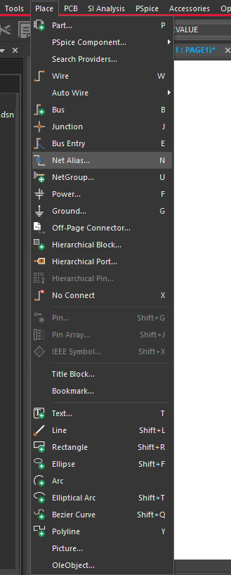
Step 16: Select Place > Net Alias from the menu, the Net Alias button on the toolbar, or press N on the keyboard.
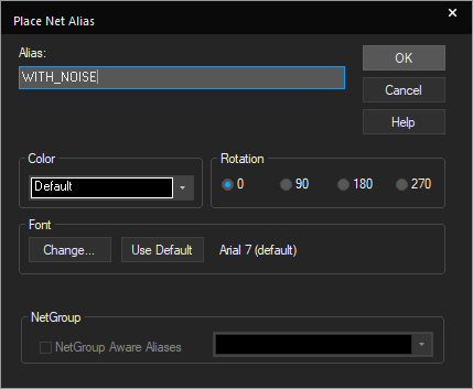
Step 17: Enter WITH_NOISE as a net alias and click OK.
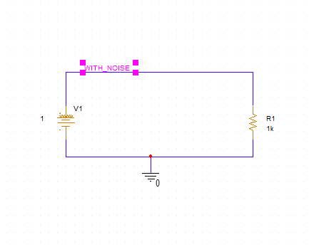
Step 18: Click to place the net alias above V1. Right-click and select End Mode.
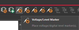
Step 19: Select the Voltage/Level Marker button from the toolbar.
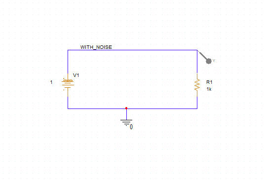
Step 20: Place a probe on the WITH_NOISE net.
Note: Rotate the voltage probe as needed by pressing R on the keyboard.
Simulating with Noise
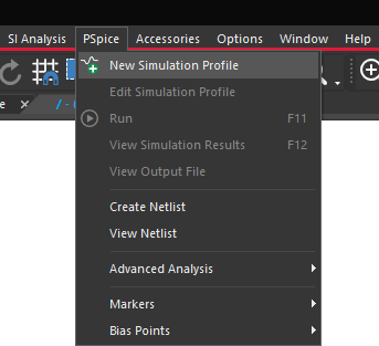
Step 21: Select PSpice > New Simulation Profile from the menu.
Step 22: Name the simulation NOISE_TRANS and click Create.
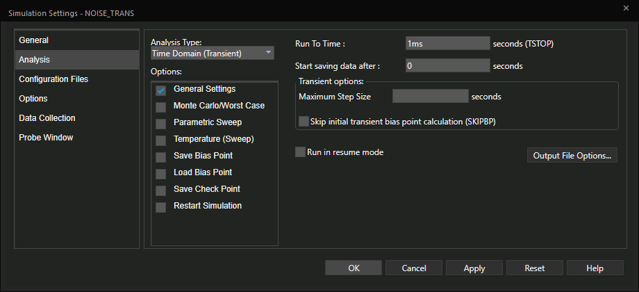
Step 23: Set the Run To Time to 1ms and click OK.
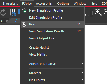
Step 24: Select PSpice > Run from the menu or the Run button from the toolbar.
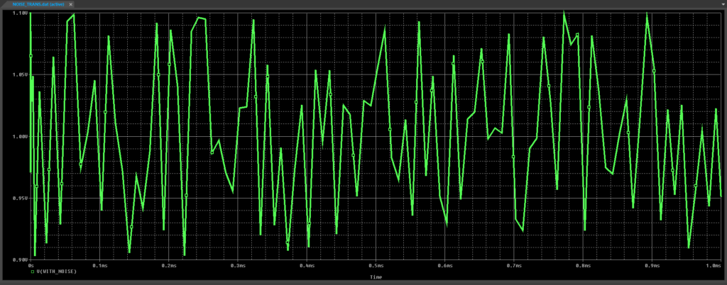
Step 25: View the results. A signal with random noise is generated.
Using Randomization Functions (RNDR)
The RNDR randomization function returns a random value between 0 and 1, which is held for the entire simulation run. This can be used in transient or DC analysis.
To follow along with this tutorial, continue with the design from Part 1 or use the provided Random_Noise.obj file.
Adding a Voltage Source
Step 1: Open the schematic in OrCAD PSpice.
Step 2: Select the noise source, V1, and press Delete on the keyboard.
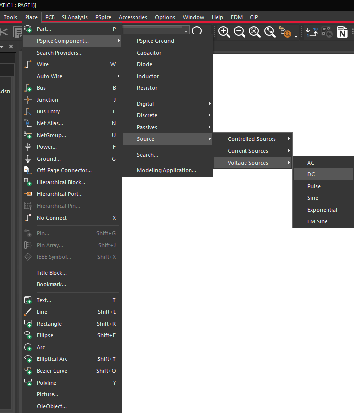
Step 3: Select Place > PSpice Component > Source > Voltage Sources > DC from the menu.
Step 4: Click to place the source and complete the wiring.
Note: To delete wires, select a wire and press Delete on the keyboard. To place wires, select W on the keyboard and click to place. Use Escape on the keyboard when finished.
Placing an Analog Behavioral Model
Step 5: Select Place > PSpice Component > Search from the menu.
Note: This will open the PSpice Part Search window.
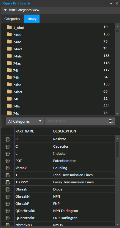
Step 6: Select the Library tab.
Step 7: Select the folder labeled abm to view the Analog Behavioral Models.
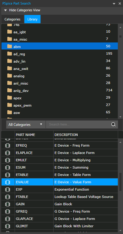
Step 8: Scroll down and select the model EVALUE.
Note: To quickly locate this model, type EVALUE in the search bar and press Enter.
Step 9: Double-click EVALUE and click to place as shown in the schematic. Right-click and select End Mode.
Completing the Circuit
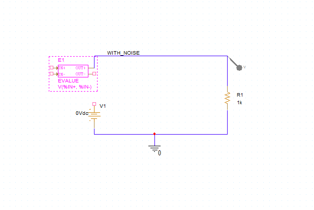
Step 10: Select Place > Wire from the menu (W).
Step 11: Wire in the new analog behavioral model as shown. Use Escape on the keyboard when finished.
Step 12: Double-click the expression in the EVALUE schematic symbol.
Step 13: For the expression value, enter (RNDR-0.5)/5 and click OK.
Step 14: Double-click 0Vdc on the DC source and set the value to 1V.
Step 15: Select Place > Net Alias from the menu, the Net Alias button on the toolbar, or press N on the keyboard.
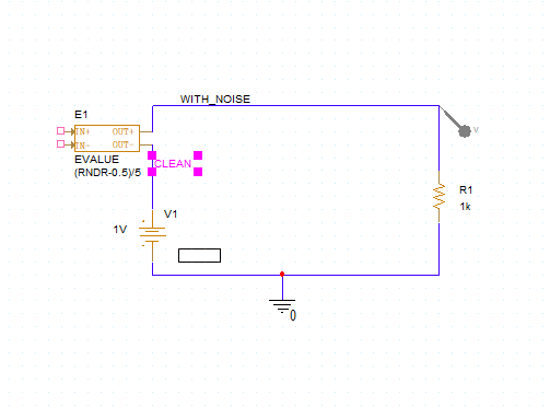
Step 16: Enter CLEAN as a net alias and click OK. Place the net alias between V1 and E1.
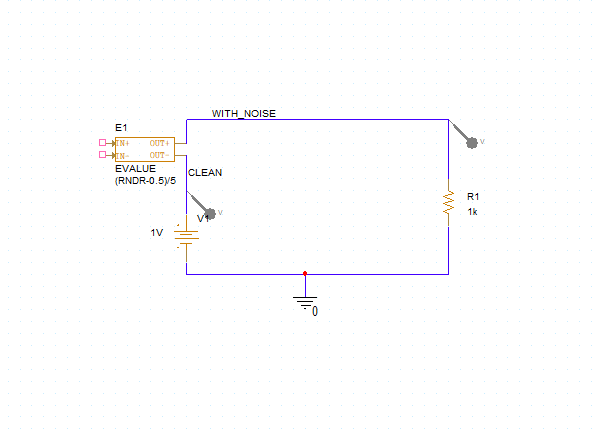
Step 17: Select the Voltage/Level Marker button from the toolbar. Place a probe on the CLEAN net. Right-click and select End Mode.
Simulating with RNDR
Step 18: Select PSpice > Run from the menu or the Run button from the toolbar.
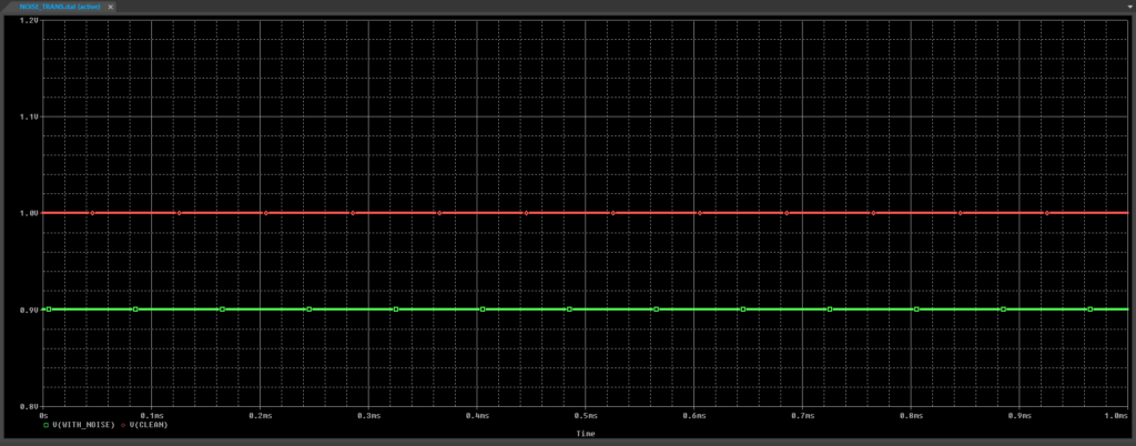
Step 19: View the results. The transient output selected and applied a single value for the duration of the simulation.
Note: To improve visibility of the difference between V(WITH_NOISE) and V(CLEAN), adjust the Y axis using the following steps:
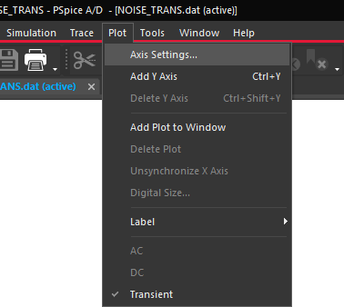
- Select Plot > Axis Settings from the menu.
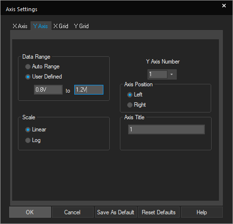
- Select the Y Axis tab.
- Under Data Range, select User Defined.
- Set the range to 0.8V to 1.2V. Click OK.
Using Randomization Functions (RNDC)
The RNDC randomization function is used to sweep through a variable or parameter. This can be used to create some variation between sweeps in Monte Carlo Analysis, DC Sweep Analysis, Temperature Sweep Analysis, and more.
To follow along with this tutorial, continue with the design from Part 2 or use the provided Random_Noise2.obj file.
Modifying the ABM
Step 1: Open the schematic in OrCAD PSpice.
Step 2: Double-click the expression in the EVALUE schematic symbol.

Step 3: Change the expression to (RNDC-0.5)/5. Click OK.
Step 4: In the PSpice Part Search Window, select the folder labeled special.
Note: If the PSpice Part Search window is not open, select Place > PSpice Component > Search from the menu and select the Library tab.
Incorporating Parameters
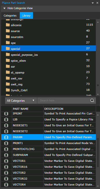
Step 5: Select PARAM from the library and double-click to attach to the cursor.
Step 6: Click to place the parameter list on the schematic. Right-click and select End Mode.
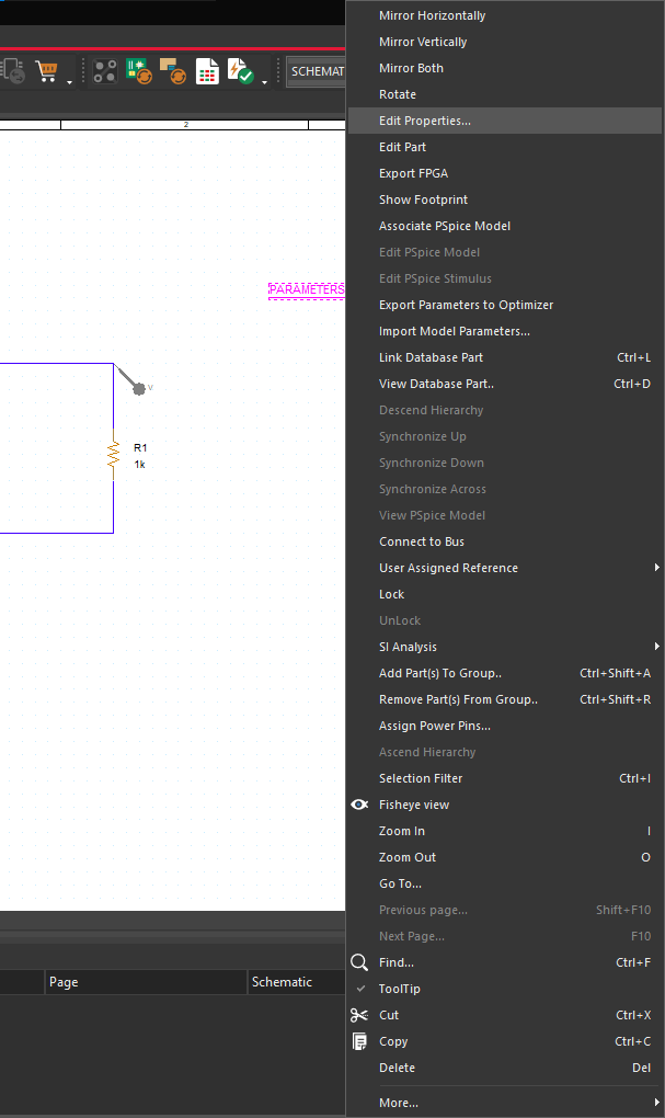
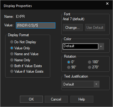
Step 7: Right-click on the parameter list and select Edit Properties.
Step 8: Select New Property.

Step 9: Add SWEEP as the name and 1 as the value. Check Display [ON/OFF] and click OK.
Step 10: The Display Properties window will open. Select Name and Value under Display Format and click OK.
Step 11: Select Apply and close out of the Property Editor window.
Simulating with RNDC
Step 12: Select PSpice > New Simulation Profile from the menu. Name the simulation NOISE_DC and click Create.
Step 13: Change the Analysis Type to DC Sweep. Select Primary Sweep.
Step 14: Select Global Parameter as the sweep variable and add SWEEP as the parameter name.
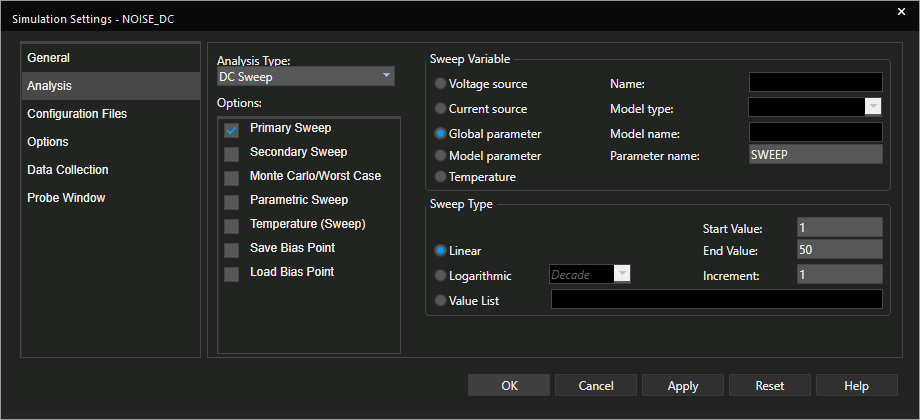
Step 15: Add 1 as the start value, 50 as the end value, and 1 as the increment. Click OK.
Step 16: Select the Voltage/Level Marker button from the toolbar.
Step 17: Click to place a probe on the CLEAN net and another on the WITH_NOISE net.
Note: Rotate the voltage probes as needed by pressing R on the keyboard.
Step 18: Select PSpice > Run from the menu or the Run button from the toolbar.
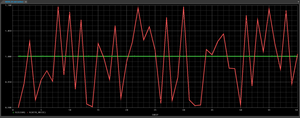
Step 19: View the results.
Wrap Up & Next Steps
Simulating noise is vital to analyze realistic circuit behavior. Quickly verify circuit functionality in the field by incorporating randomization functions and easily configurable noise sources in OrCAD PSpice. Learn how you can easily simulate, analyze, and optimize your circuit functionality with a free trial.

