Once the component placement is completed in the PCB design, the connections need to be made by routing traces. With the number of connections in today’s designs, in order to route boards and adhere to strict time constraints, there must be efficient routing options. OrCAD X Presto allows you to quickly route boards with:
- Easily configurable fanouts
- Interactive routing
- Delay and phase tuning
- Assisted routing
- Hug and Shove options
- Clearance views
- Group routing
- And more
This quick how-to will provide step-by-step instructions on how to route boards in OrCAD X Presto using fanouts, interactive routing, differential pair routing, delay tuning, and group routing.
To follow along, download the provided files above the table of contents.
How-To Video
 Open in New Window
Using Fanouts in OrCAD X Presto
Step 1: Open the provided design, Presto_Demo1A.brd, in OrCAD X Presto.
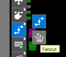
Step 2: Right-click on the Add Connect icon on the toolbar and select Fanout.
Note: The fanout graphic displays helpful information to configure the desired fanout. In this window, you can set the fanout pattern, direction, trace width, spacing and more depending on the configuration.
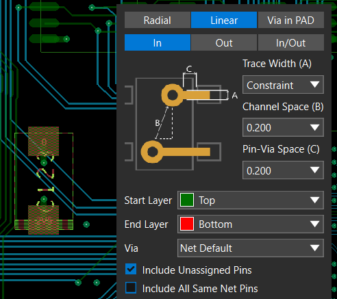
Step 3: In the fanout pop-up, select Linear and In.
Step 4: Click to select component C123. View the fanout.
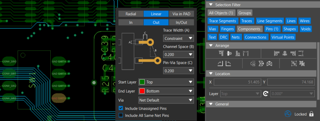
Step 5: Back in the fanout window, select the Out.
Step 6: In the Selection Filter in the properties panel, click Components to deselect it.
Step 7: Click to select pins 5, 6, 7, and 8 on SW1. Only the selected pins have been fanned out and connected to ground.
Note: Pan the view on the PCB canvas using the arrow keys as needed to view SW1.
Step 8: In the Selection Filter, choose Components to turn the selection on again.
Route Boards in OrCAD X Presto
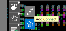
Step 9: Right-click the Fanout icon and select the Add Connect icon from the toolbar.
Step 10: In the Add Connect window, select Assisted. The assisted mode helps to avoid design rule errors while routing.
Step 11: Configure the Add Connect window with the desired settings. Here you have the ability to:
- Define trace width
- Define working layers
- Select to hug or shove traces
- Define the preferred angle lock (0, 45, or 90)
Slide the smoothing bar to the desired automatic smoothing of traces.
Step 12: Use the left arrow key to pan the view to see U6 then click to select pin 38 on U6. Since this is a surface mount part the layer is automatically set as Top. Click X to hide the Add Connect window.
Step 13: Zoom in with the + key on the keyboard. Click to place a short trace then press V on the keyboard to add a via.
Note: Vias can also be activated by double clicking in the PCB canvas. View all the pre-configured shortcuts, change hotkeys, and assign hotkeys by selecting Edit > Preferences > System > Shortcuts (Hotkeys) from the menu.
Step 14: Select Inner1 from the list. The via has been placed in the PCB canvas.
Step 15: Click the PCB canvas as needed to place the trace then click to complete the connection.
Using Shove to Route a Board in OrCAD X Presto
Step 16: Click to select pin 37 on U6. The layer is automatically set back to Top.
Step 17: Click to place a short trace then press V on the keyboard to add a via.
Step 18: Select Inner1 from the list. The via has been placed in the PCB canvas.
Step 19: Select X on the keyboard to bring up the Add Connect window, then select the option to Shove traces.
Step 20: Click the PCB canvas as needed to place the trace then click to complete the connection. Any traces or trace segments are shoved out of the way to complete the connection.
Step 21: Select the Arrow icon from the toolbar when finished then click a blank area in the PCB canvas.
Configuring Ratsnest Visibility in OrCAD X Presto
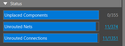
Step 22: In the Properties Panel, view the design status and select the hyperlink for Unrouted Nets.
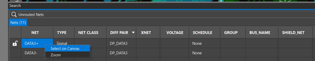
Step 23: The search panel opens at the bottom of the screen for you to easily review the unrouted connections. This search panel can be filtered and sorted to find the desired objects in the PCB canvas. Double-click the differential pair column (Diff Pair) to bring all differential pairs to the top of the list.
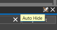
Step 24: Right-click on the first entry and choose Select on Canvas or double-click the entry in the search panel. The PCB canvas pans and zooms to the location of the differential pair. Select the Pin icon twice to hide the search panel.
Step 25: Select the Visibility tab and choose the Net display. Here you can configure ratsnest visibility and change the color of nets in the PCB canvas.
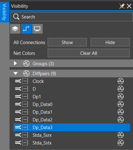
Step 26: Click the arrow next to Differential Pairs to expand the Differential Pair category.
Step 27: Click the ratsnest icon for Dp_Data3.
Note: Selecting the ratsnest icon at the top level, such as groups or differential pairs, will turn on the ratsnest lines for all items in the corresponding group.
Step 28: Click the Visibility tab to close the panel then use the arrow keys on the keyboard to pan the view to show the activated differential pairs. Click a blank space in the PCB canvas to deselect the traces.
Routing Differential Pairs in OrCAD X Presto
Step 29: Select the Add Connect icon from the toolbar.
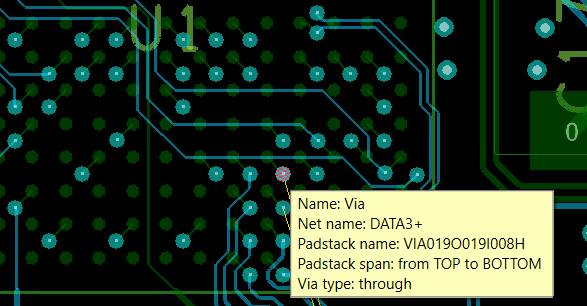
Step 30: Zoom in as needed with the + key on the keyboard, then click to select one of the Data3 nets on U1. Both traces are activated.
Note: These have been defined as differential pairs and constraints have been assigned in the constraint manager. For more information on assigning and constraining differential pairs in OrCAD X Presto, view our walk-through with step-by-step instructions.
Step 31: In the Add Connect window, ensure Inner1 is selected from the Start Layer drop-down list. Click to place the trace in the canvas and click to place the connection.
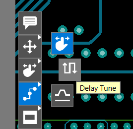
Step 32: Right-click on the Slide icon in the toolbar and select Delay Tune.
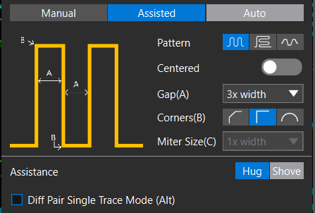
Step 33: In the Delay Tune window, select Assisted and set the corners as Square. Leave all other values as the default.
Note: The graphic displays helpful information to configure the desired delay tuning. In this window, you can set the Pattern, Gap, Corners, Miter Size and more depending on the configuration.
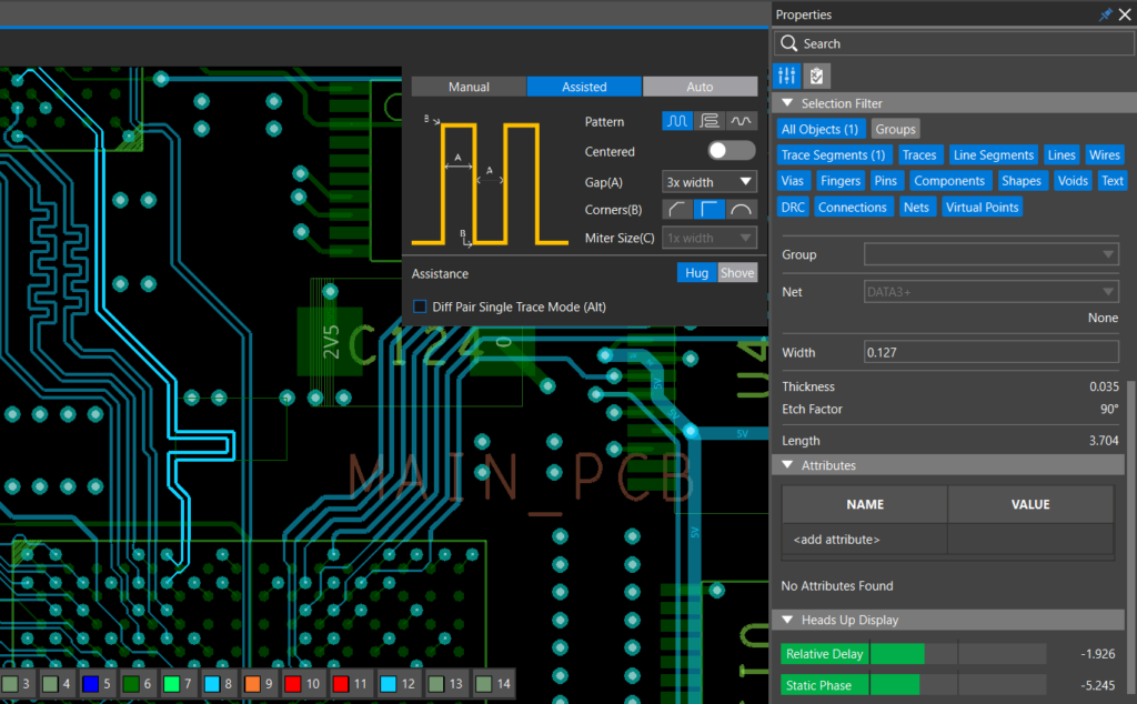
Step 34: Click to select a portion of the differential pair trace.
Step 35: In the Properties Panel, scroll down to the bottom to view a heads-up display when routing. This display provides real-time feedback on adherence to rules including relative propagation delay.
Step 36: Move the cursor to add delay tuning to the differential pair until the relative propagation delay and static phase are both green in the heads-up display. Click to place the trace.
Routing Groups in OrCAD X Presto
Step 37: Select the Add Connect icon on the toolbar then use the arrow keys, + and – on the keyboard to adjust the PCB canvas and view the ratsnest still visible of the flex portion of the design.
Step 38: In the Add Connect window, ensure the Start Layer is set to Inner1 and change the trace type to Arc.
Step 39: Highlight the vias near the flex portion of the board and click one of the vias to start routing. Press X on the keyboard to hide the Add Connect window.
Step 40: Click to place the traces following the flex shape. When close to connector, P2, press ESC on the keyboard.
Step 41: Press X to bring up the Add Connect window and change the trace type to straight.
Step 42: Click to complete each connection by selecting a trace and selecting the corresponding pin on P2.
Step 43: Select the Arrow icon on the toolbar when finished.
Wrap Up & Next Steps
Quickly route boards using interactive routing, fanouts, and more in OrCAD X Presto. Don’t have OrCAD X Presto? Get your free trial and for more step-by step instructions and walk-throughs on using OrCAD X Presto visit EMA Academy.
