Prebuilt symbols, footprints, and 3D models greatly accelerate the product design process, as the time required to build and verify models is increasing due to component complexity. Ultra Librarian provides millions of verified component models, allowing you to focus on the PCB design instead of model creation and create an accurate CAD library; however, sometimes models need to be adjusted to better suit your company standards and design preferences. EDABuilder helps you accelerate CAD model creation with easy import of models from Ultra Librarian and features to efficiently modify schematic symbols including:
- Component Checks to Identify Errors and Warnings
- Fast Creation of Symbol Sections
- Easy Arrangement and Modification of Pins
- Size and Shape Editing
- Style Templates and Settings
This quick how-to will provide step-by-step instructions on how to import and modify schematic symbols with EDABuilder.
How-To Video
 Open in New Window
Import Ultra Librarian Models into EDABuilder
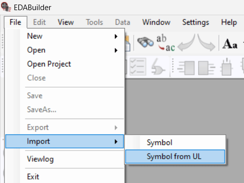
Step 1: Open EDABuilder and select File > Import > Symbol from UL.
Note: If the Ultra Librarian login opens, login in with your Ultra Librarian username and password. This how-to and functionality requires an Ultra Librarian subscription to access millions of prebuilt and verified component models. Don’t have an Ultra Librarian account? Sign up for free here.
Step 2: The Import Symbol from UL window opens. In the Manufacturer dropdown, select Cypress Semiconductor.
Note: Quickly find the desired manufacturer by beginning to type the manufacturer name in the drop-down menu.
Step 3: In the Part Number field, enter CY101 and select Search.
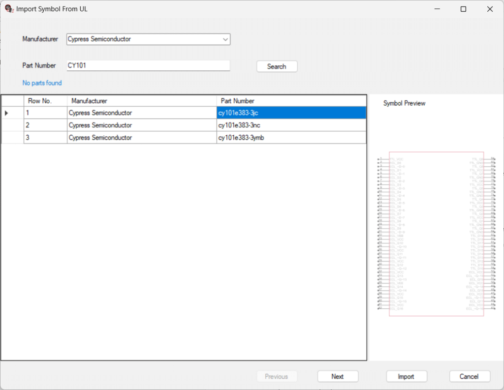
Step 4: View the returned parts and select cy101e383-3jc to view a preview of the symbol.
Step 5: Select Import.
Verify Component Information
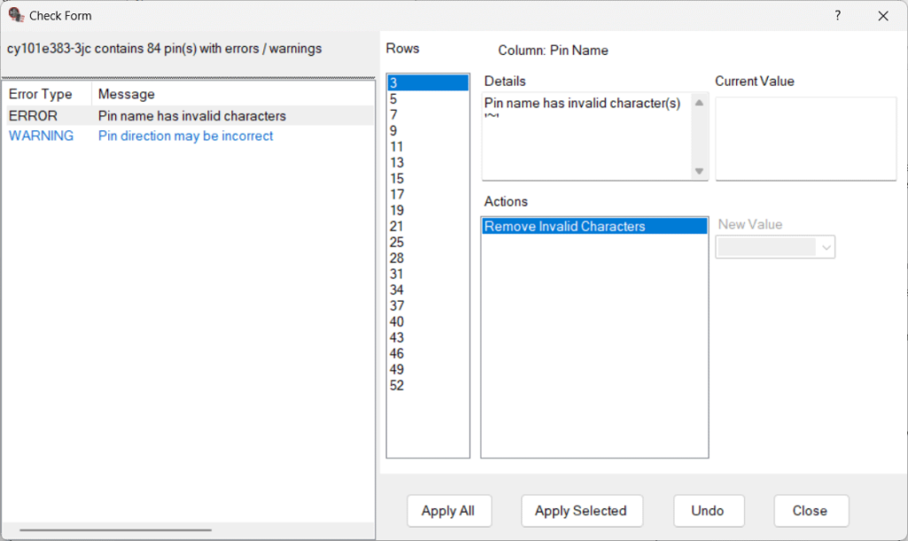
Step 6: The Check form will appear reporting any errors or warnings found within the part. This window can be used to quickly identify, review, and resolve any issues. View the errors. For this example, the component model has used an invalid character in some pin names.
Step 7: In the Actions section, ensure Remove Invalid Characters is selected and select Apply All to remove the invalid character from all pins reported in the rows section.
Step 8: View the next warning in the list. For this example, the direction for TTL_GND has not been defined.
Step 9: Select the different rows to review all the pins this has been reported for.
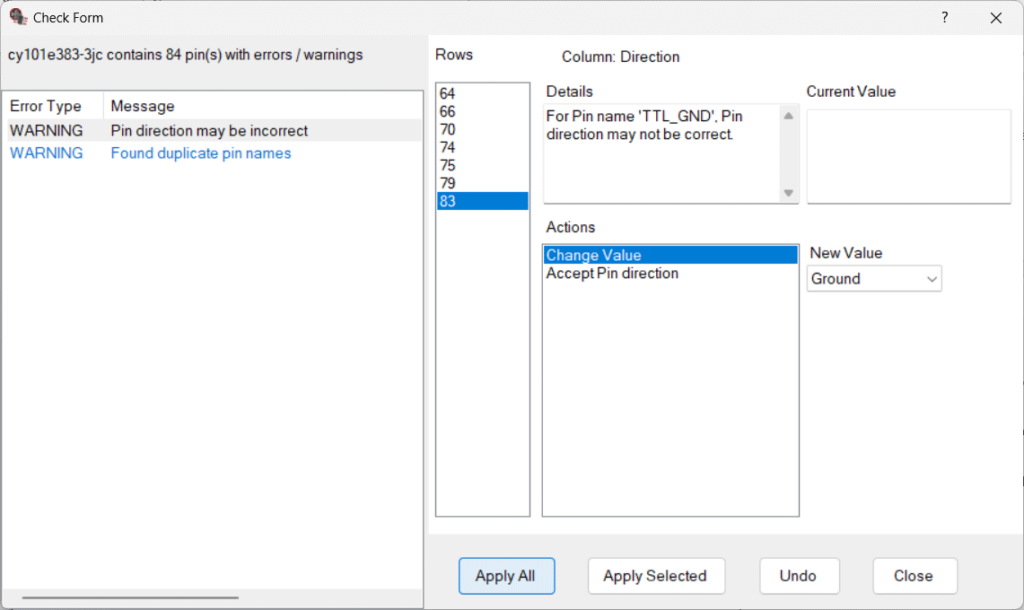
Step 10: Under Action, ensure Change Value is selected. Under New Value, ensure Ground is selected from the dropdown.
Step 11: Select Apply All.
Step 12: View the final warning in the list. For this example, duplicate pin names have been used for several pins in the symbol. This pin naming structure was done intentionally to reflect the functionality of the component, so it can be ignored.
Step 13: Select Close to ignore the warning.
Modify Schematic Symbols: Create Symbol Sections
Note: The symbol can now be modified based on your style and functional preferences. The following steps will provide examples of some potential modifications.
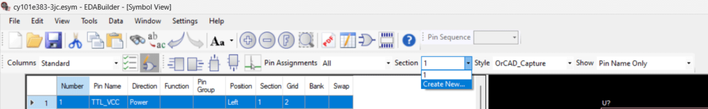
Step 14: Under the Section drop-down menu, select Create New. This will create a new section of the schematic symbol allowing clearer definition of pins.
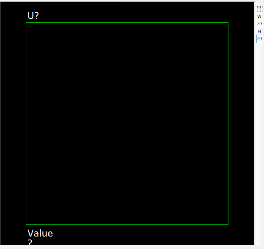
Step 15: In the Width and Height section, define the Height (H) as 20.
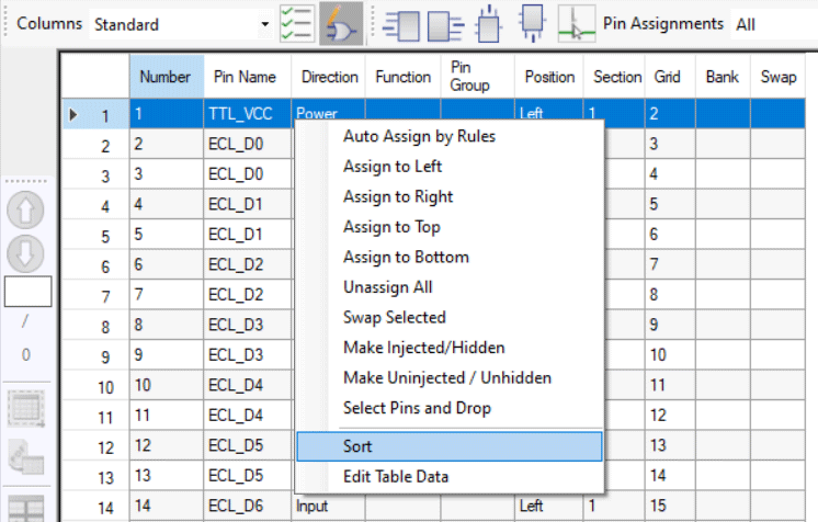
Step 16: Right-click in the Pin Table and select Sort.
Step 17: In the Sort By drop-down menu, select Direction and Close.
Step 18: View the sorted pin information. Scroll down to the Power and Ground sections in the table.
Step 19: In the Pin table, click and drag to highlight the pins defined as power and ground.
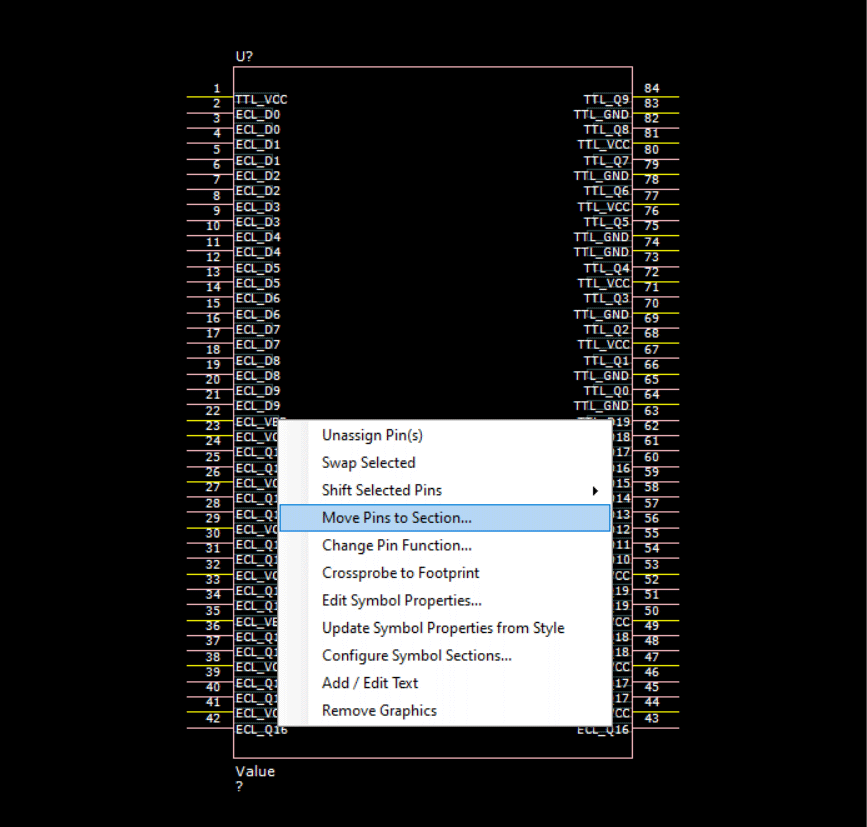
Step 20: In the component view, right-click on a selected pin and choose Move Pins to Section.
Step 21: In the pop-up window, select 2 to move the power and ground pins to the second section of the schematic symbol.
Step 22: In the Section dropdown, select 2 to view the second section of the component model.
Step 23: Pin 84, TTL_Q9, was moved by mistake. Select pin 84 TTL_Q9 in the symbol view. Right-click and select Move Pins to Section.
Step 24: In the pop-up window, select 1 to move the pin to section 1.
Modify Schematic Symbols: Organize Pins
Step 25: Select Pin 1, TTL_VCC, in the schematic symbol. Click and drag to the desired location on the symbol and release the mouse button.
Step 26: In the schematic symbol view, highlight the ECL_VCC pins on the right of the symbol. Click and drag the pins to the left and release the mouse.
Step 27: Complete this process to configure the pins in the schematic symbol as desired.
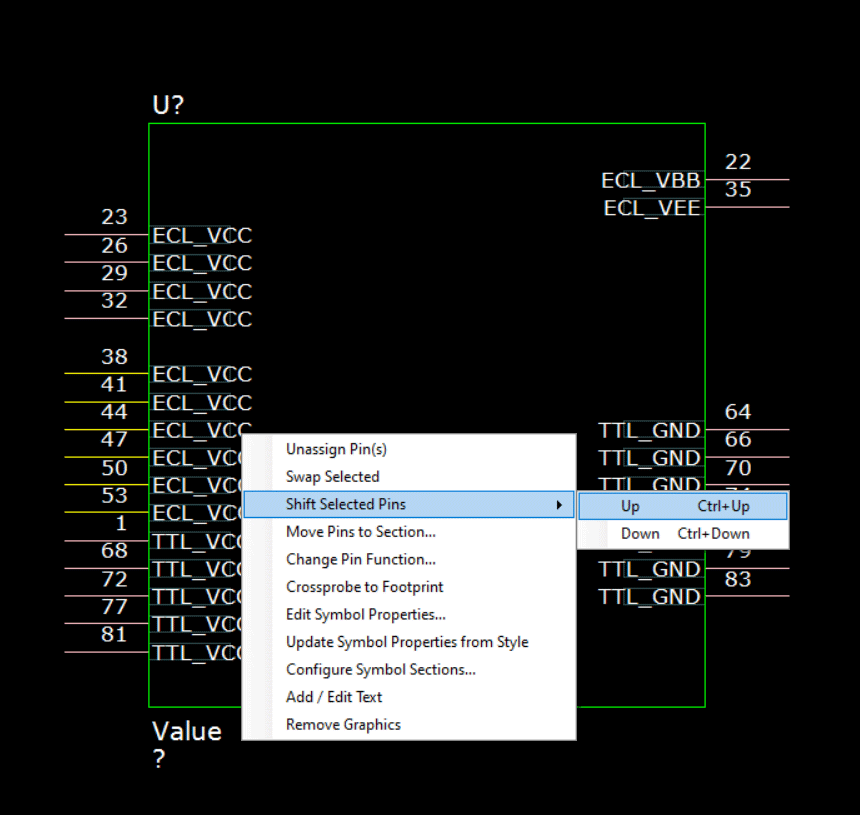
Step 28: Highlight pins 38, 41, 44, 47, 50 and 53. Right-click and select Shift Selected Pins > Up or press CTRL + Up Arrow Key.
Step 29: Highlight pins 22 and 35. Right-click and select Shift Selected Pins > Down (CTRL + Down Arrow Key). Repeat this process as needed until section 2 is completed.
Note: Sometimes when moving pins, the height and width of the schematic symbol is automatically adjusted. If this has occurred, reset the height and width of the symbol to 20.
Step 30: In the Section dropdown, select 1 to navigate to the first section of the schematic symbol.
Step 31: Select pin 84, TTL_Q9. Click and drag to the desired location on the symbol and release the mouse button.
Modify Schematic Symbols: Component Size
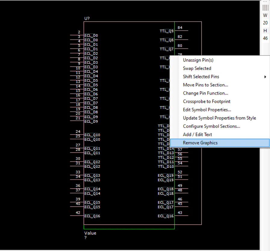
Step 32: In the Width and Height Section, define the Width (W) as 20.
Step 33: Right-click and select Remove Graphics.
Modify Schematic Symbols: Style
Step 34: In the Style drop-down select OrCAD_Capture. This will export the component model in the defined style format.
Note: The following styles are included by default:
- Allegro Design Authoring
- Allegro System Capture
- DX Designer
- OrCAD Capture
- PADS Logic
Custom style settings can be configured before schematic symbol creation outlining the desired company preferences and can be used as a template to standardize schematic symbol appearance. Learn how to configure the schematic symbol style here.
Export Schematic Symbols from EDABuilder
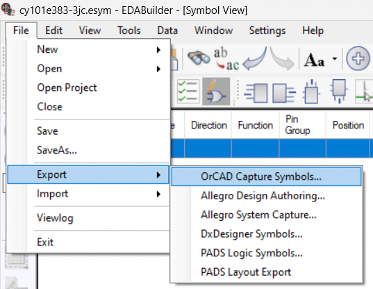
Step 35: Select File > Export > OrCAD Capture Symbol.
Note: EDABuilder includes additional export options for varying CAD formats including:
- Allegro Design Authoring
- Allegro System Capture
- DX Designer Symbols
- PADS Logic Symbols
- PADS Layout Export
Step 36: A prompt will appear to save the project before exporting, select Yes.
Step 37: Select Browse. Browse to the desired location and click OK.
Step 38: Click OK to create the new symbol.
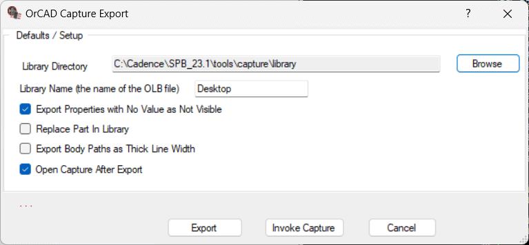
Step 39: Under Library Directory, select Browse. Browse to the library and click OK.
Step 40: Enter a name for the library.
Step 41: Check the box for Open Capture After Export to launch OrCAD Capture to view the symbol after the export has completed.
Step 42: Select Export.
Step 43: In the pop-up window, select OrCAD Capture or your desired software package and click OK.
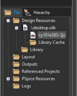
Step 44: In the project hierarchy in OrCAD Capture, double click the schematic symbol.
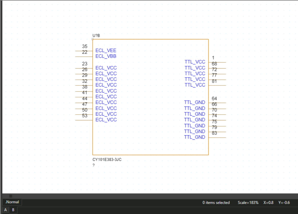
Step 45: View the created schematic symbol. Select section B to view the second section of the symbol.
Note: Learn how to add, access, and use libraries in OrCAD Capture with our step-by-step walk-through.
Wrap Up & Next Steps
Efficiently modify schematic symbols from Ultra Librarian with direct import and easy-to-use features in EDABuilder to create consistency throughout your designs. Get more step-by-step instructions for EDABuilder at EMA Academy.

