With today’s designs becoming more compact, ensuring that all components fit on the PCB without interference and within the mechanical housing is a crucial step in the design process. Using components that are too large or placing a connector even slightly off-center can lead to costly and time-consuming respins. New in OrCAD X Presto 24.1 is the ability to quickly map 3D models to any component on the board in the 3DX canvas and map mechanical models to obtain a realistic representation of your PCB assembly and analyze your PCB in 3D.
This quick how-to will provide step-by-step instructions on how to quickly map 3D models with the 3DX canvas in OrCAD X Presto.
To follow along, download the provided files above the table of contents.
How-To Video
 Open in New Window
Activate the 3DX Canvas
Step 1: Open the provided design in OrCAD X Presto.
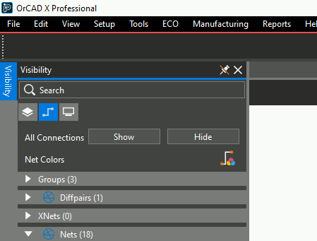
Step 2: Select Visibility to open the Visibility panel.
Note: If the Visibility button is not visible, select View > Panels > Visibility from the menu.
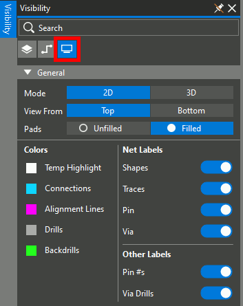
Step 3: Select the Display mode in the Visibility panel to configure global visibility settings.
Step 4: Select 3D to activate the 3DX canvas.
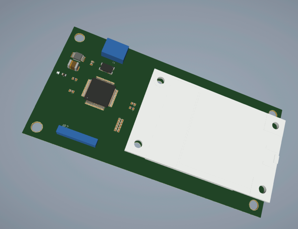
Step 5: Pan the 3D canvas view by clicking and dragging the middle mouse button. Rotate the view by holding Shift while clicking and dragging the middle mouse button.
Note the missing connectors on the front and back of the board with the blue placement boundary. These will be added in the following steps.
Activate 3D Mapping
Step 6: In the 3DX canvas in Presto, select View > Panels > 3D Model Mapper from the menu.
Step 7: The 3D Model Mapper tab is shown. If the panel is not opened automatically, select the button to open it.
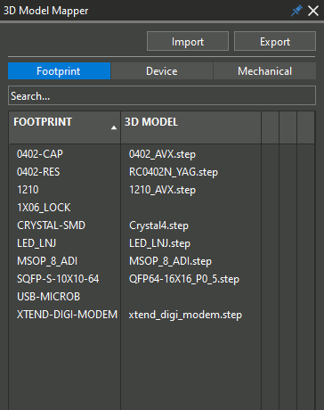
Step 8: View the 3D Model Mapper panel. 3D models are missing from connectors 1X06_LOCK and USB_MICROB. These are the components shown with placement boundaries.
Map 3D Models in OrCAD X Presto
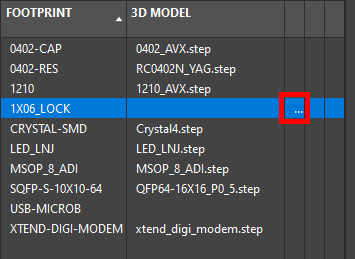
Step 9: We will start by loading a 3D model for connector 1X6_LOCK. Hover over 1X6_LOCK in the 3D Model Mapper panel. Select the ellipsis to open the file browser. The 3D view automatically pans over the connector.
Step 10: Browse to the working directory and select the provided conn1x6.step file. Click Open.
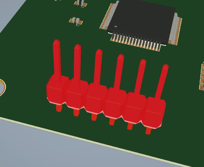
Step 11: Hold Shift on the keyboard and drag the middle mouse button to rotate for a better view of the model. The 3D model has been successfully mapped.
Map 3D Models With Adjustments
Note: While many 3D models map to the component footprint correctly with no adjustments required, some 3D models are offset or not mapped properly when loaded. Such models can be adjusted in the 3D Model Mapper tab with the following steps.
Step 12: Hover over USB-MICROB in the 3D Model Mapper panel. Select the ellipsis to open the file browser.
Step 13: Browse to the working directory and select the provided USB_MicroAB.STEP and click Open.
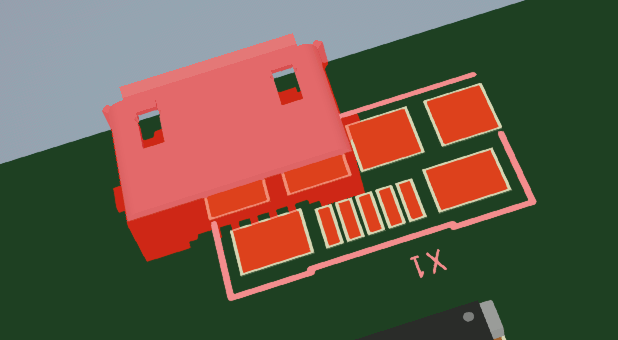
Step 14: View the mapped model in the canvas. The 3D model was loaded correctly but is not aligned with the footprint. It will be mapped correctly in the following steps.
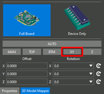
Step 15: View the bottom of the 3D Model Mapper panel. A set of buttons for mapping components and text fields are visible.
Note: The following mapping options are also available:
- Manual: Manually adjust the model by clicking and dragging in each axis.
- Top: Snap the selected face of the model to the top of the board.
- Bottom: Snap the selected face of the model to the bottom of the board.
- XY: Snap a feature of the model to a feature of the footprint in the X and Y axes.
- Z: Snap a feature of the model to a feature of the footprint in the Z axis.
Step 16: Select the XY button to map the USB connector in the X and Y axes. The view is panned to a top view of the connector. Select one of the pins on the footprint.
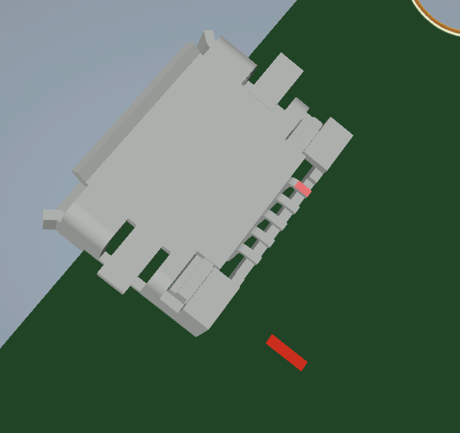
Step 17: Pan to the bottom of the 3D model and select the corresponding pin. The selected pins are highlighted in red.
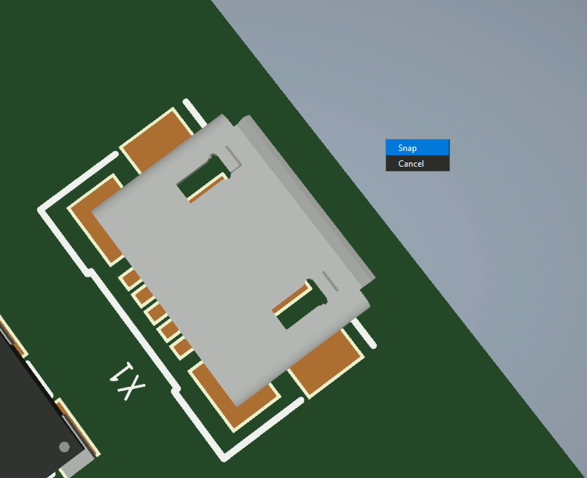
Step 18: Right-click and select Snap. The connector is snapped to the footprint in the X and Y directions, but still needs to be aligned in the Z direction.
Step 19: To align the connector in the Z direction, select the Z mapping option.
Step 20: Select a pin on the connector footprint, then rotate the view and select the corresponding pin on the 3D model.
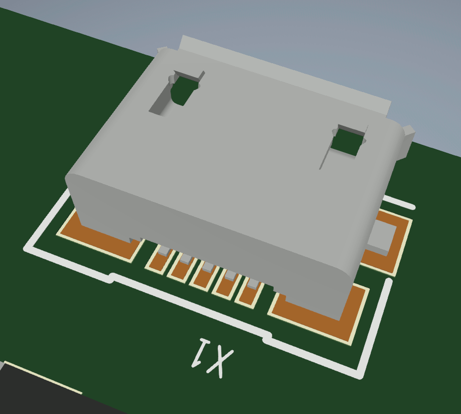
Step 21: Right-click and select Snap. The connector is properly mapped to the footprint in all three dimensions.
Step 22: To return to the 2D view, select Visibility and choose the 2D mode. The 2D view is restored.
Wrap Up & Next Steps
Quickly map 3D models to ensure fitment for your board and first-pass success with the 3DX Canvas in OrCAD X Presto. Test out this feature and more with a free trial of OrCAD X. For more how-tos and step-by-step walkthroughs, visit EMA Academy.