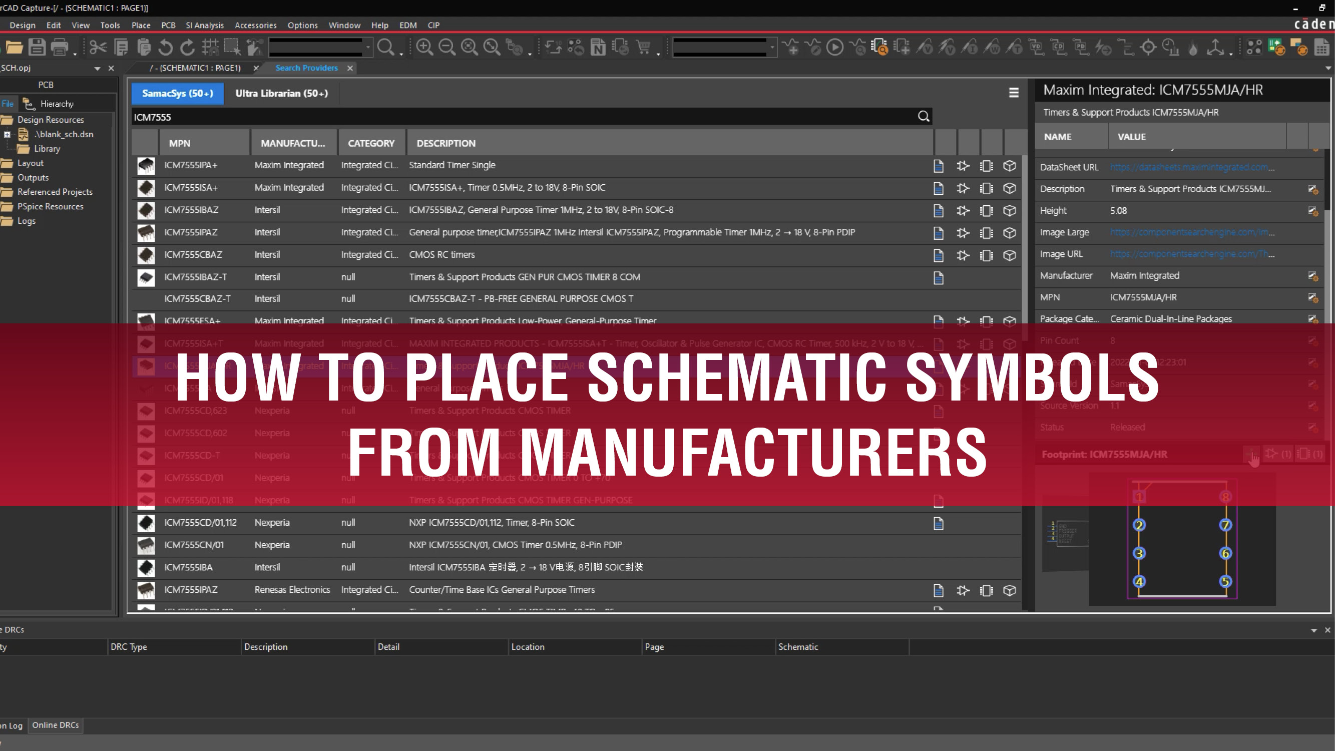
Accurate symbols, footprints, and 3D models are required for PCB designs; however, default libraries may not contain the parts you need and manually creating and verifying all the necessary models can be time-consuming. OrCAD Capture 17.4 provides integrated access to extensive, verified libraries allowing you to efficiently search and place schematic symbols from manufacturers, like Ultra Librarian and SamacSys, directly within your design environment.
This quick how-to will provide step-by-step instructions on how to place schematic symbols from manufacturers with the Search Providers feature in OrCAD Capture 17.4.
Not using OrCAD 17.4? Learn how to place schematic symbols in a newer version of Capture here.
How-To Video
 Open in New Window
Activate the Search Providers Tab
Step 1: Open a blank design in OrCAD Capture 17.4.
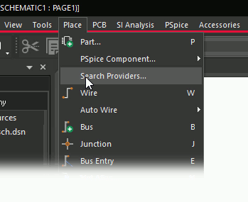
Step 2: Select Place > Search Providers from the menu.
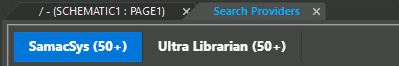
Step 3: If prompted, enter your Cadence and Ultra Librarian credentials and click Sign In. The Search Providers tab has two subpanels for SamacSys and Ultra Librarian.
Place Schematic Symbols from Manufacturers: SamacSys
Step 4: Select the SamacSys tab.

Step 5: Enter ICM7555 into the Search field and press Enter to search.
Note: Each part has a set of symbols to indicate whether it has a schematic symbol, PCB footprint, datasheet, and 3D model.
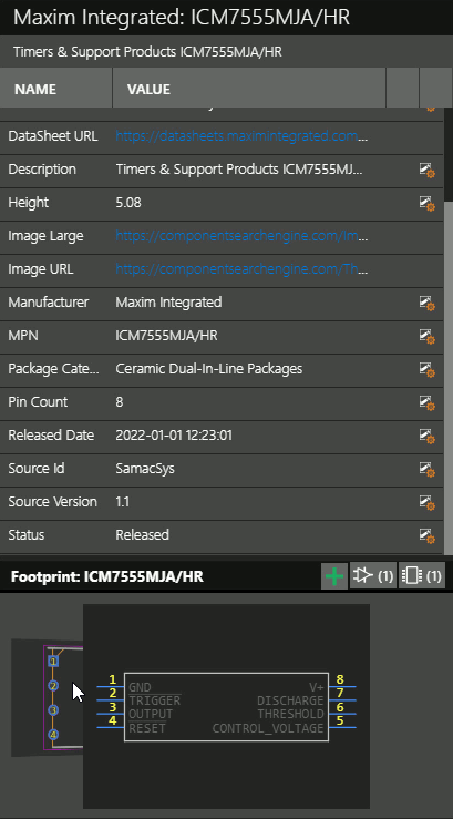
Step 6: Select a part and view its properties on the right side of the window. The properties subpanel shows additional part information and a preview of the schematic symbol and footprint, if provided.
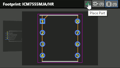
Step 7: Select the plus sign in the properties subpanel. The corresponding schematic symbol, footprint, and 3D model are automatically downloaded and mapped and the part is attached to your cursor.
Step 8: Click to place the part in the schematic. Right-click and select End Mode.
Place Schematic Symbols from Manufacturers: Ultra Librarian
Step 9: Select the Search Providers tab at the top of the canvas.
Step 10: Select the Ultra Librarian tab.
Step 11: Enter LM324 into the search bar and press Enter to search.
Note: The Search field can also be used to search for keywords in the component’s description.
Step 12: Select a part and select the plus sign to attach it to your cursor.
Step 13: Click to place the part in the schematic. Right-click and select End Mode.
View the PCB Footprint
Note: The PCB footprint and 3D model can be viewed in the schematic’s corresponding board file. Since one does not exist for this design, we need to create it.
Step 14: Select PCB > New Layout from the menu to create a new board file. The New Layout window opens.
Step 15: Leave the settings as the defaults and click OK.
Note: For more information on generating a PCB layout, view our how-to here.
Step 16: The Product Choices window opens. Select the appropriate license and click OK.
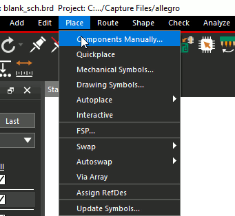
Step 17: OrCAD PCB Designer opens. Select Place > Components Manually from the menu.
Step 18: In the Placement window, check Components by RefDes to place all components in the design.
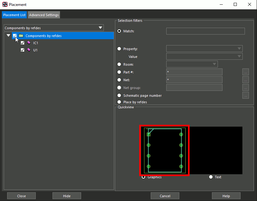
Note: A preview of the next footprint to be placed is shown at the bottom of the window.
Step 19: Click to place the parts in the PCB canvas. Right-click and select Done.
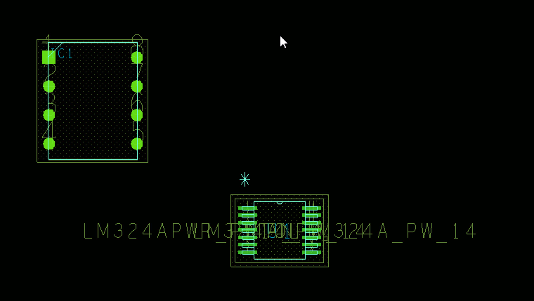
Step 20: View the placed components. The footprints match those downloaded from the Search Providers.
View the 3D Models
Step 21: To view the downloaded 3D models, select Display > 3D Canvas from the menu.
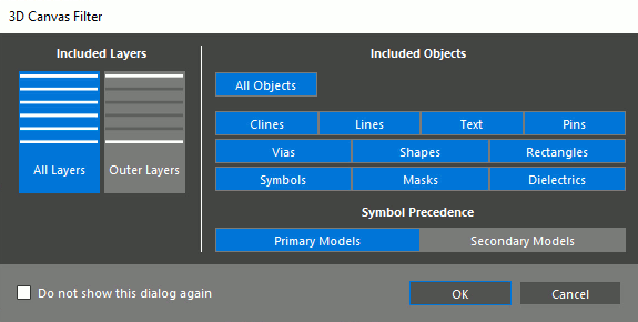
Step 22: The 3D Canvas Filter window opens. Here, you can configure which objects, layers, and models are shown. Leave the default settings and click OK.
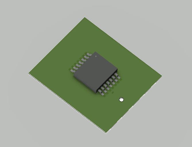
Step 23: View the mapped models in the 3D canvas. Use the middle mouse button to pan the view and hold Shift with the middle mouse button to rotate it.
Wrap Up & Next Steps
Quickly place schematic symbols from manufacturers and leverage the extensive libraries of Ultra Librarian and SamacSys with Search Providers in OrCAD Capture.
Don’t have Capture? Get a free trial of OrCAD.
Want to learn more about Capture? Get access to free how-tos, courses, and walk-throughs at EMA Academy.

