With today’s designs becoming more compact, flex and rigid flex PCBs are becoming more common. While rigid flex PCBs are versatile and useful to adhere to the mechanical requirements of the project, routing through flex portions of the design can be difficult as traces must conform to irregular shapes. With OrCAD X Presto you can perform contour routing which allows for quick and easy routing of traces in flex zones by contouring to the curves and irregular shapes, ensuring that each trace follows the path of the flex zone.
This quick how-to will provide step-by-step instructions on how to perform contour routing in OrCAD X Presto to efficiently route rigid flex PCBs.
To follow along, download the provided files above the table of contents.
How-To Video
 Open in New Window
Activate Routing
Step 1: Open the provided design in OrCAD X Presto Professional.

Step 2: Select the Add Connect mode from the toolbar.
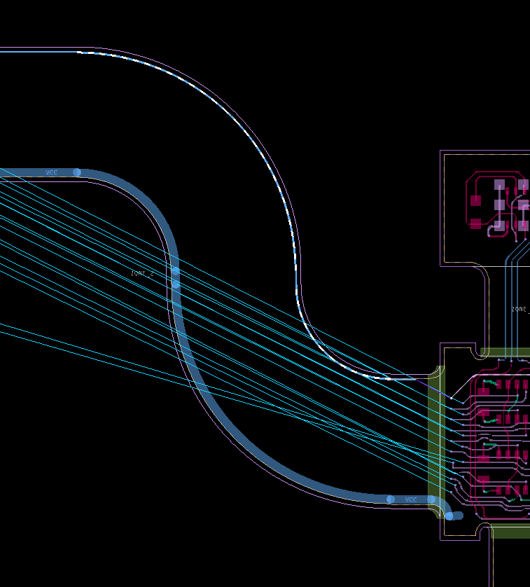
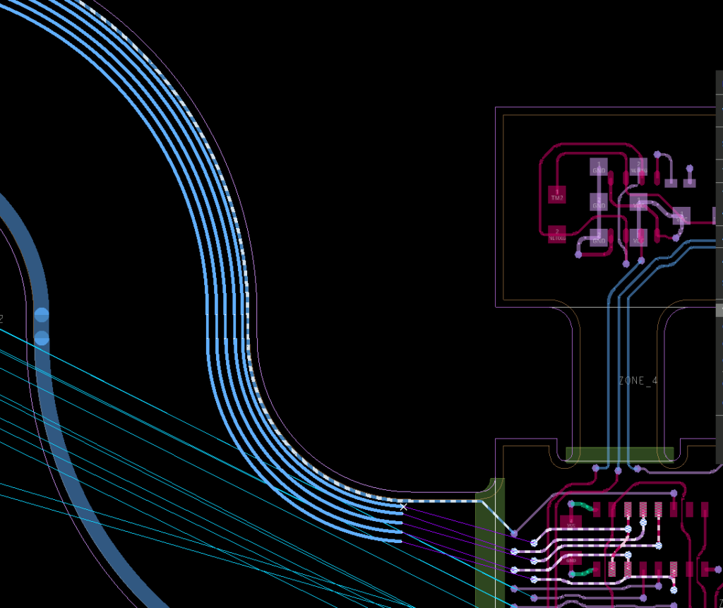
Step 3: Zoom into the via for A_1 at the top of the rigid flex. Click the via to start routing.
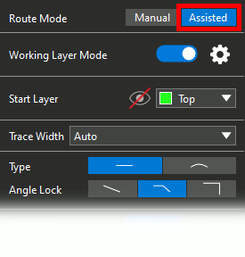
Step 4: In the Add Connect widget, make sure Assisted is selected.
Step 5: Select Flex_1 from the Start Layer dropdown.
Note: If you are unable to select this layer, you may have accidentally clicked the A_1 trace, not the via. Press Escape to cancel routing and click the via again.

Attempting to route this trace in the rigid flex zone without the contour mode activated will bend it at a 45° angle at the curve.
Configure Contour Routing
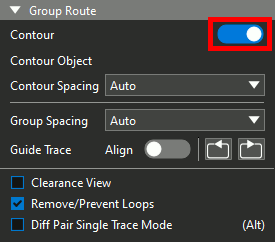
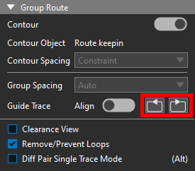
Step 6: Under Group Route, enable the toggle for Contour.
Step 7: Select Constraint from the Contour Spacing dropdown to route the contour as close to the reference trace as allowed by the constraint set.
Note: Other options for contour spacing include:
- Auto: Route the new trace at the distance from the reference it was started.
- Value: Route the new trace at a set distance from the reference.
Perform Contour Routing: Single Trace
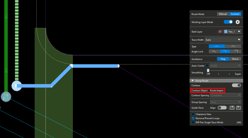
Step 8: Click the route keepin. The keepin is assigned as the Contour Object in the Add Connect widget. The trace attached to your cursor automatically snaps to the contour of the keepin and rigid flex outline.
Note: If the keepin is not visible, open the Visibility panel and select the eye for Conductor Keep-In or Route Keep-In under Geometries.
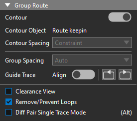
All contour options are locked when a contour object is assigned. The contour mode remains active even if the toggle is grayed out.
Step 9: Move your cursor to the bottom of the rigid flex zone. The trace is locked to the path of the flex shape.
Note: If you make a mistake, use the backwards and forwards arrows to undo and redo the routing of traces.
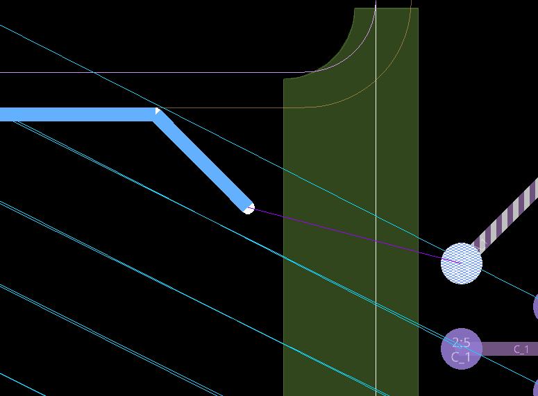
Step 10: Click to place the trace. The trace is released from the contour and can be freely routed as normal.
Step 11: View the ratsnest line connecting the unfinished trace and via. Click to finish the trace at the A_1 via at the bottom of the board.
Perform Contour Routing: Multiple Traces
Step 12: Pan the view back to the top of the rigid flex zone.
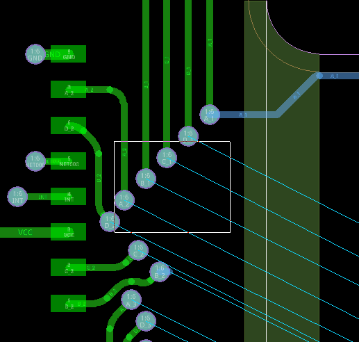
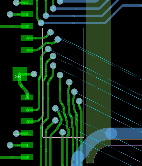
Step 13: Click and drag to select the vias for nets D_1, C_1, B_1, A_2, and D_2.
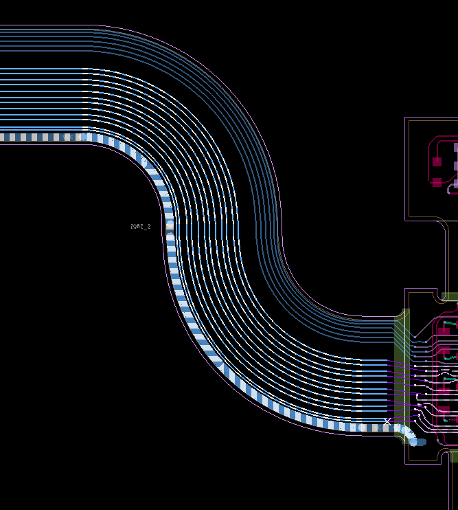
Step 14: In the Options panel, under Group Spacing, enter 25 to route the traces at 25 mils apart from each other.
Note: Be sure to configure the spacing options as desired before routing, the options will lock once routing starts.
Step 15: Click the uppermost via to start routing. Traces for all five selected nets are attached to the cursor.
Step 16: Click to route the group horizontally.
Step 17: Select the routed trace for A_1 to route the group on its contour.
Step 18: Move the mouse to the bottom of the rigid flex zone and click to place the traces. Each trace follows the contour of A_1 and the rigid flex. Press Escape to finish routing.

Step 19: Click to route each trace to its respective via in the lower zone and click again to finish.
Finish the Rigid Flex Routing
Step 20: Pan the view back to the top of the flex zone.
Step 21: Click and drag to select the remaining vias with ratsnest lines between the two zones.
Step 22: Click the lowest via to start routing. Click the large VCC trace at the bottom of the rigid flex to assign it as the contour reference.
Step 23: Click the lower portion of the rigid flex to finish routing and press Escape. All rigid flex traces have been routed, following the contour of the rigid flex zone.
Step 24: Click each trace to connect it to its respective via in the lower zone.
Wrap Up & Next Steps
Quickly and efficiently perform contour routing on flex and rigid-flex PCBs to route traces according to the design outline in OrCAD X Presto. Test out this feature and more with a free trial of OrCAD X. For more how-tos and step-by-step walk-throughs, visit EMA Academy.

