Determining the optimal values for components for a design is critical as the value of each component will have an effect on the circuit output; however, fine-tuning component values manually can be tedious and lengthen the time spent on simulation, which may push your project off-schedule. With PSpice Designer Plus, quickly optimize circuits and fine-tune the values for multiple components to achieve your desired circuit output.
This quick how-to will provide step-by-step instructions on how to optimize circuits by automatically identifying the ideal component values to achieve your desired functionality in PSpice Designer Plus.
To follow along, download the provided files above the table of contents.
How-To Video
 Open in New Window
Loading a Demo Design
Step 1: Open PSpice Designer Plus.
Step 2: Select File > Open > Demo Designs from the menu.
Step 3: The Open Demo Designs window opens. Scroll down and select RF Amplifier.
Step 4: Click Open to open the design.
Note: If this design has been modified on your system, download the clean version provided above the table of contents.
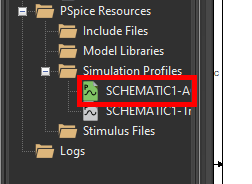
Step 5: In the Project Manager, under Simulation Profiles, verify that SCHEMATIC1-AC is highlighted in green, indicating it is the active profile.
Note: If SCHEMATIC1-AC is not the active profile, right-click and select Make Active.
Running the Simulation
Step 6: A simulation must be run before optimization can be performed. Select PSpice > Run from the menu to start the simulation.
Note: The simulation is pre-defined in this example. To learn how to configure and run a new simulation in PSpice, see our how-to here.
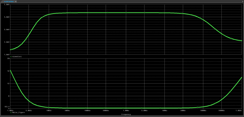
Step 7: View the AC Sweep results. The output noise from 1kHz to 1GHz is plotted.
Creating Measurements
Step 8: A measurement to optimize must be defined. To define a measurement, select View > Measurement Results from the menu.
Note: Component values can also be optimized from a pre-defined curve. To learn more about curve optimization, see our PSpice Advanced Analysis Level 2 workshop here.

Step 9: The Measurement Results subpanel opens. Select Click Here to Evaluate a New Measurement to create a new measurement.
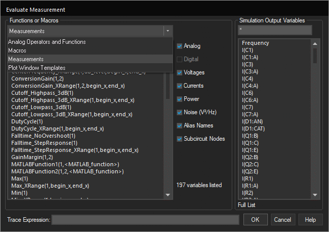
Step 10: The Evaluate Measurement window opens. Select Measurements from the Functions or Macros dropdown.
Step 11: Select Max(1) from the Measurements list.
Step 12: Select Analog Operators and Functions from the Functions or Macros dropdown. Select DB() from the list.
Step 13: Select V(Load) from the Simulation Output Variables list.
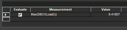
Step 14: Click OK to add the measurement. The measurement is added to the Measurement Results subpanel and the value is calculated.
Step 15: Select Click Here to Evaluate a New Measurement again to add a new measurement.
Step 16: Copy the expression Bandwidth(V(Load),3) and paste it in the Trace Expression box.
Step 17: Click OK to add the measurement.
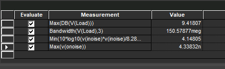
Step 18: Repeat steps 15-17 for the following expressions:
Min(10*log10(v(inoise)*v(inoise)/8.28e-19))Max(v(onoise))
Step 19: Close the PSpice A/D window.
Optimize Circuits: Configuration
Step 20: Back in the schematic canvas, select PSpice > Advanced Analysis > Optimizer from the menu.
Note: If the PSpice Advanced Analysis Product Choices window opens, select the appropriate license and click OK.
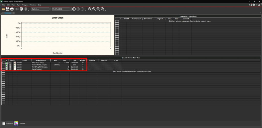
Step 21: The PSpice Advanced Analysis window opens. In the Specifications [Next Run] subpanel, ensure that all measurements defined in PSpice were imported.
Note: Perform the following steps if the table is blank.
Step 1: Select Click Here to Import a Measurement Created Within PSpice.
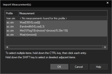
Step 2: Hold CTRL and click each measurement to select all. Click OK to add the measurements.
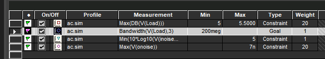
Step 22: Each cell for each measurement can be adjusted. Double-click a cell to change its contents or select an option from the dropdown. Change the specification table to match what is shown above.
Note: Measurements can be defined as goals or constraints. A goal defines the measurement result that the Optimizer should attempt to meet. A constraint defines a measurement range that the design must fulfill.
Step 23: Before the Optimizer can be run, the parameters to adjust must be defined as well. In the Parameters [Next Run] table, select Click Here to Import a Parameter from the Design Property Map.
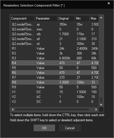
Step 24: Scroll down to the component values section. Hold CTRL and select R8, R6, and R4 to add them as parameters. Click OK.
Step 25: Set the minimum and maximum values for R8 to 3 and 3.6.
Step 26: Set the minimum and maximum values for R6 to 235 and 705.
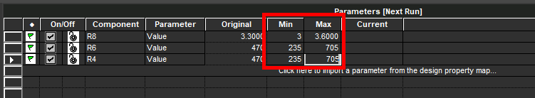
Step 27: Set the minimum and maximum values for R4 to 235 and 705.
Optimize Circuits
Step 28: With the measurements and parameters defined, the Optimizer can be run. Select Run > Start Optimizer from the menu.
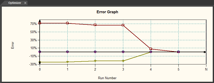
Step 29: The Optimizer runs and plots the results on the Error Graph. If the Optimizer is able to converge on a solution, each line will approach 0.
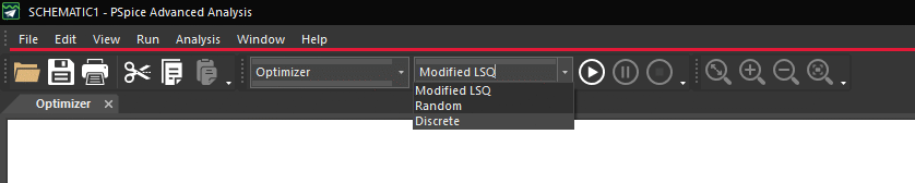
Step 30: The optimized values can be rounded to the nearest purchasable component. Select Discrete from the Simulation Engine dropdown.
Step 31: The Discrete Table column is added. Select Resistor – 5% from the dropdown for each component.
Step 32: Select Run > Start Optimizer from the menu again to start the optimizer.
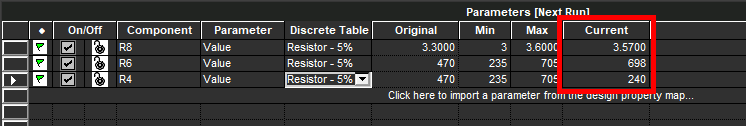
Step 33: View the parameter table. The value of each resistor is changed to the nearest purchasable value.
Adjusting the Component Values
Step 34: Minimize the PSpice Advanced Analysis window.
Step 35: Back in the schematic, double-click the value for R8 to change it.
Step 36: Enter 3.57 for the value and click OK.
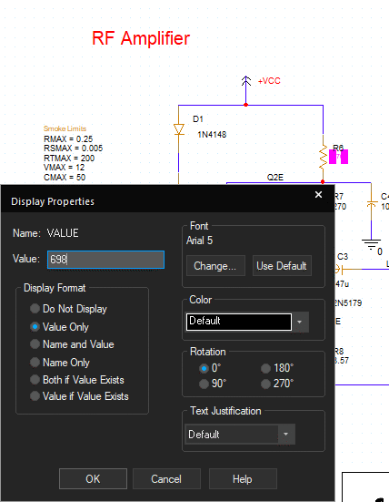
Step 37: Double-click the value for R6 to change it. Enter 698 for the value and click OK.
Step 38: Double-click the value for R4. Enter 240 for the value and click OK.
Optimize Circuits: Verification
Step 39: Select PSpice > Run from the menu to rerun the simulation.
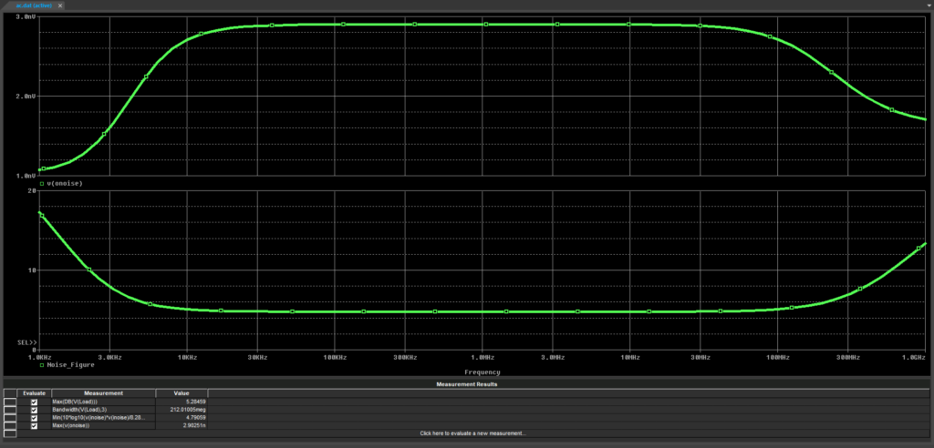
Step 40: View the plot and measurements. The bandwidth increased as desired and the other measurements stayed within specifications.
Wrap Up & Next Steps
Quickly optimize circuits by determining the ideal purchasable component values with the Optimizer in PSpice Designer Plus. Test out this feature and more with a free trial of OrCAD. Want to learn more about the Optimizer and the other advanced analysis options in PSpice? View the Level 1 and Level 2 PSpice Advanced Analysis workshops.

