For a PCB designer, learning a new tool can be a daunting task, to say the least. User interfaces can vary widely, and the capabilities of the tool may not be readily apparent to a beginner. OrCAD X Presto provides a simple and intuitive, yet powerful interface that is ideal for both new and seasoned designers with enhanced features including:
- Simplified toolbars for easy access of commands
- Widgets with visual graphics for efficient configuration of design elements
- Properties panel providing a unified location for editable information
This quick how-to will provide step-by-step instructions on how to navigate the OrCAD X Presto user interface to help you become familiar with the new design environment and streamline your design process.
To follow along, download the provided files above the table of contents.
How-To Video
 Open in New Window
Navigate the OrCAD X Presto User Interface: Visibility
Step 1: Open the provided or desired design in OrCAD X Presto.
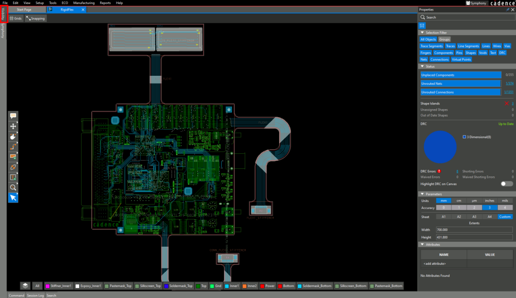
Step 2: View the OrCAD X Presto canvas. The Visibility panel is located on the left. Click the button to open it.
Note: If this panel is not visible, select View > Panels > Visibility from the menu.
Step 3: OrCAD X Presto uses an intuitive three-panel system for easy navigation of layer, net, and design visibility. Scroll through the panel to view the Layer mode visibility settings. A list of copper and other board layers is shown.
Step 4: To enable or disable a copper layer, select the space under All to turn the layer on or off. To enable or disable another layer, select the eye icon.
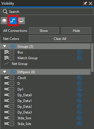
Step 5: Select the Nets mode. All nets, Xnets, differential pairs, and net groups are listed. Net colors and visibility can be defined here.
Step 6: Right-click a net color. Select a color to assign it to a net. This will aid in efficient identification of specific nets in the PCB canvas.
Step 7: Select the ratsnest icon to turn off the ratsnest for Sel. Select the ratsnest icon again to turn the ratsnest on again.
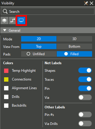
Step 8: Select the Display mode. From this mode, you can adjust the board view.
Note: Available settings in the Display mode include:
- View the top and bottom side of the board
- Colors for common elements such as connections and backdrills
- Label Visibility
- Shadow Mode
- Global and Object Opacity
Step 9: Select 3D to view the board in 3D.
Step 10: Right-click and select Toggle 2D/3D.
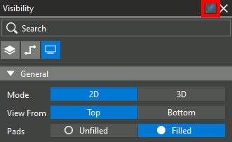
Step 11: Select Auto Hide to keep the Visibility panel on screen.
Step 12: Click and drag the top of the panel to detach it from the sidebar. The panel can be moved anywhere on screen, giving you more room in the design canvas if your system has multiple monitors.
Note: To reattach the panel, hover it over its original location. The area will be highlighted in blue. Any panel can be detached from the Presto window.
Navigate the OrCAD X Presto User Interface: Properties Panel
Step 13: View the Properties panel on the right side of the canvas. The panel shows global design parameters such as unplaced components, DRCs, and units.
Step 14: Select a component on the board. The Properties panel is now populated with component properties such as location, footprint, and layer.
Step 15: Select a trace segment on the board. The Properties panel is populated with the segment length and width.
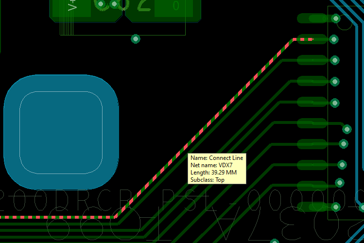
Step 16: Hover your mouse over the segment and press Tab on the keyboard. The entire trace is highlighted.
Note: The Tab key can be used to cycle through elements under your cursor. Alternatively, turn off undesired elements in the Selection Filter subpanel of the Properties panel. For example, if trying to select a trace, disable Trace Segments in the Selection Filter.
Step 17: Click to select the trace. The information shown in the Properties panel is similar to that of the trace segment, but now shows a segment count and a much longer trace length.
Step 18: Hover your mouse over the segment and press Tab again. The net is highlighted. Click to select the net.
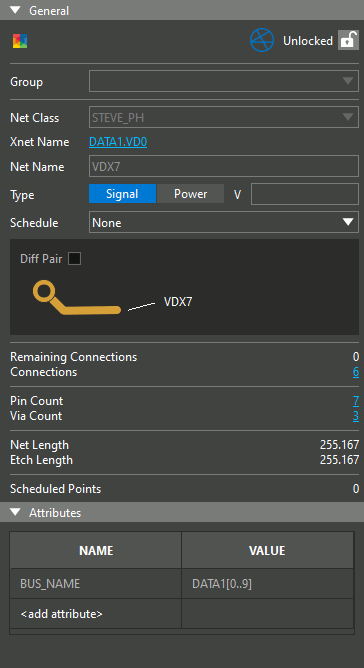
Note: The Properties panel now shows information on the net, including single ended/differential pair, signal or power, voltage if applicable, and total connection count.
Step 19: Click a blank area of the canvas to deselect the net.
Navigate the OrCAD X Presto User Interface: Search Panel
Step 20: In the Status subpanel of the Properties panel, select the hyperlink for Unrouted Nets.
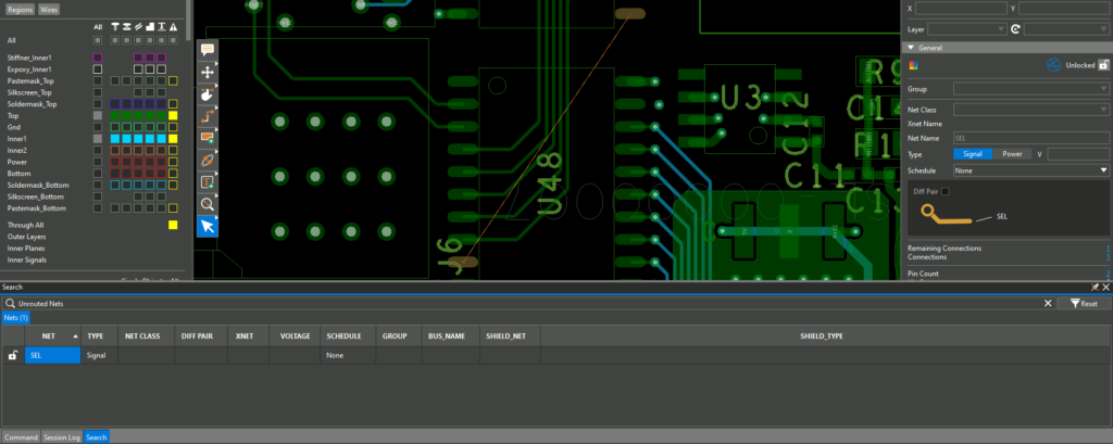
Step 21: The Search panel opens at the bottom of the window, showing the unrouted nets. Double-click a net to be brought to its location.
Step 22: Click a blank area of the canvas to deselect the net.
Step 23: Select the hyperlink for Unrouted Connections in the Status subpanel.
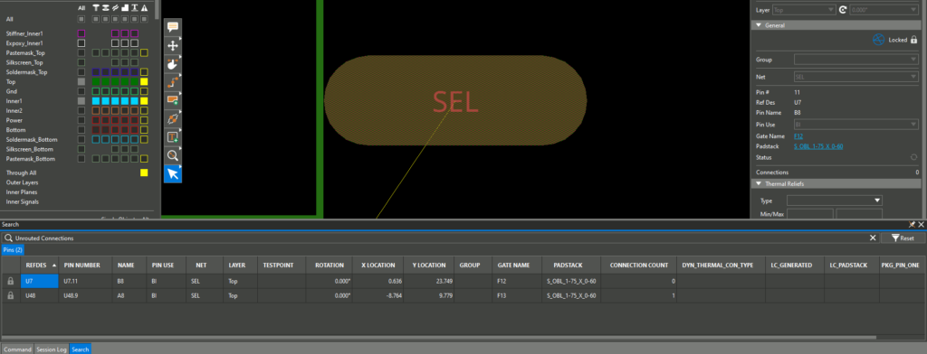
Step 24: The Search panel now shows the unconnected pads. Double-click a pad to be brought to its location. Click a blank area of the canvas to deselect the pad.
Note: To zoom out, press – on the keyboard or scroll the mouse wheel down. To pan the view, hold the middle mouse button and drag or use the directional arrow keys on the keyboard.
For more information on using the Search panel in OrCAD X Presto, view our how-to here.
Navigate the OrCAD X Presto User Interface: Toolbar
Note: OrCAD X Presto includes a toolbar, allowing for quick and easy access to commonly used commands.
Step 25: Locate the toolbar in the canvas. Click and drag to adjust its position as desired.
Note: If you place the toolbar on a top or bottom edge, it is oriented horizontally.

Step 26: Several modes are listed in the toolbar. Right-click any mode with a white arrow to view a list of related modes.
Step 27: Select the Add Connect mode from the toolbar.
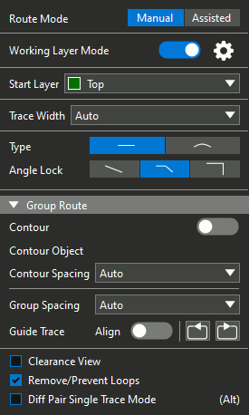
Step 28: The Add Connect widget opens in the canvas, showing all relevant options and controls for the selected mode. Select an unconnected pin to begin routing.
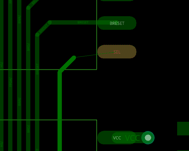
Step 29: Click to route the trace to another unconnected pin, using the ratsnest line as a guide. Click the pin when finished.
Note: For more information on routing traces in OrCAD X Presto, try our free OrCAD X Presto Walk-Through here.
Step 30: Choose the Select mode from the toolbar or press Escape on the keyboard when finished.
Wrap Up & Next Steps
Save time and make the design process easier by learning how to navigate the OrCAD X Presto user interface. Don’t have OrCAD X Presto? Get your free trial here, and for more step-by step instructions and walk-throughs on using OrCAD X Presto, visit EMA Academy.