With the complexity of today’s PCB designs, it is essential to analyze signal integrity and power integrity before production to guarantee product performance. Sigrity Aurora includes an easy-to-use translator which allows designers to quickly import Altium designs into Sigrity to perform SI and PI analysis and enables PCB designers to evaluate common SI and PI issues, regardless of the software used to design the PCB.
This quick how-to will provide step-by-step instructions on how to import Altium designs into Sigrity Aurora for SI/PI analysis.
How-To Video
 Open in New Window
Configuring the Import
Step 1: Open Sigrity Aurora and select File > Import > Altium PCB from the menu.
Note: Need help importing other CAD formats? Learn how to import a neutral IPC-2581 file here.
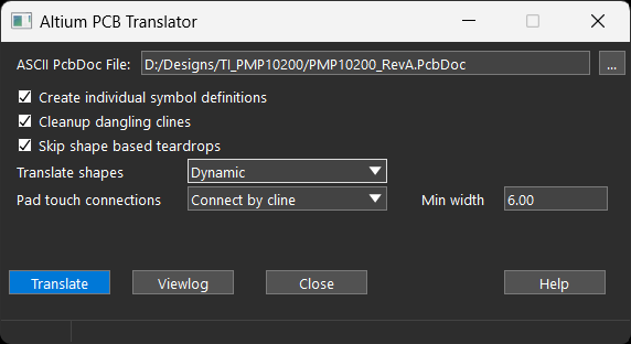
Step 2: In the Altium PCB Translator window, select the ellipsis to load an Altium board file.
Step 3: Browse to and select the file. Click Open.
Note: This file must be in the ASCII format. To save your Altium design in ASCII format, select File > Save As and select PCB ASCII File (.PcbDoc) format.

Step 4: Select the option to Create Individual Symbol Definitions. Selecting this option will generate specific symbol definitions for each footprint by adding a suffix.
Step 5: Select the option to Cleanup Dangling Clines. Selecting this option deletes clines with at least one end unconnected.
Step 6: Select Dynamic from the Translate Shapes dropdown. Selecting this option will redraw voids and copper pours. Only the shape outlines are copied.
Note: In the Static mode, voids and pours are copied as their own shape, potentially making the design harder to modify. There are several other translation options are available including:
- Skip Shape Based Teardrops: Altium generates teardrop traces from shapes and tracks. This option skips the shape-based teardrop option, as teardrops in Sigrity X and OrCAD X are parameter-driven (not shape-derived).
- Pad Touch Connections: Choose whether to connect vias and pin pads by cline, by shape, or to leave unconnected.
- Min Width: Select the minimum width for lines to be copied from Altium into Sigrity.
Import Altium Designs into Sigrity Aurora
Step 7: Select Translate.

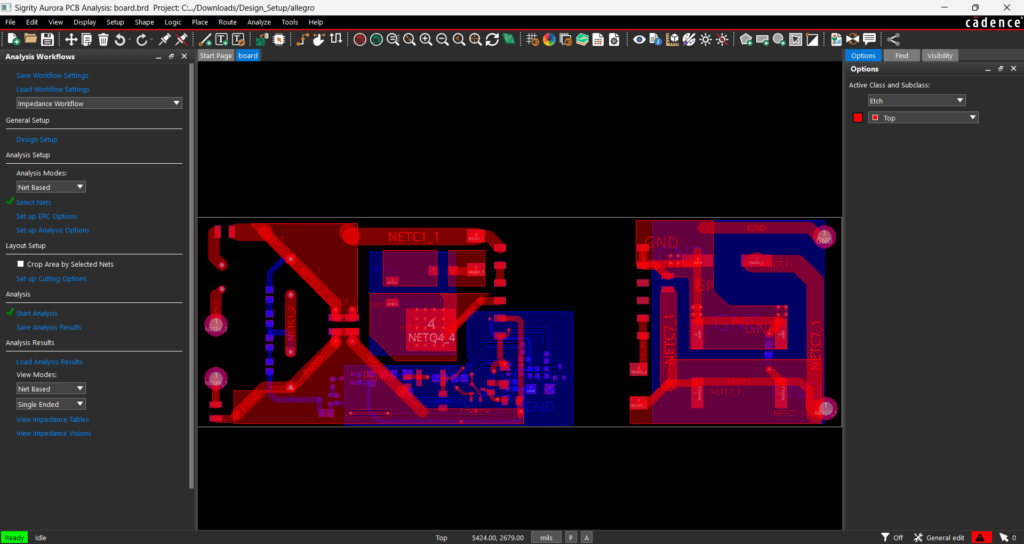
Step 8: When the translation and import finishes, the board is shown in the Sigrity canvas. Select Close in the Import window.
Performing SI/PI Analysis on Altium Designs in Sigrity Aurora
Step 9: Review the design and correct errors as needed.
Step 10: In the Analysis Workflow panel, select the desired workflow from the drop-down selection and begin the corresponding signal integrity or power integrity analysis.
Note: The workflows in Sigrity Aurora walk you through the steps required to perform:
- Impedance analysis
- Coupling analysis
- Return path analysis
- Crosstalk analysis
- Reflection analysis
- Power inductance analysis
- IR Drop analysis
- Topology extraction
- Interconnect model extraction
For more information on these common SI/PI issues and how to use Sigrity Aurora to identify and correct them, view our free workshop: Introduction to In-Design SI/PI Analysis with Sigrity Aurora.
Wrap Up & Next Steps
Quickly import Altium designs into Sigrity Aurora to translate the PCB and perform signal integrity and power integrity analysis. Don’t have Sigrity Aurora? Contact us here to request an evaluation and visit EMA Academy for more step-by-step instructions for Sigrity Aurora.