An accurate, easy to manage component database consisting of verified part data, symbols, and footprints can improve your PCB design process and increase design accuracy; however, database setup and configuration can be difficult. Import a starter database in OrCAD CIP to leverage the predefined database schema and starter library of 5,000 parts and get your component database set up quickly.
This quick how-to will provide step-by-step instructions on how to import the provided starter database in OrCAD CIP.
How-To Video
 Open in New Window
Open OrCAD CIP
Step 1: With a blank schematic created in OrCAD X Capture CIS, select CIP > Open CIP from the menu.
Step 2: If prompted, log in with your username and password.
Note: To import a starter database in OrCAD CIP, you may need administrative permissions.
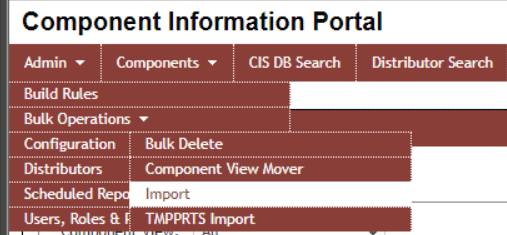
Step 3: Select Admin > Bulk Operations > Import from the CIP menu.
Upload a Starter Database to OrCAD CIP
Step 4: Select Configuration.
Step 5: Select Choose File. Browse to the desired file and click Open.
Note: To use the starter database included in the standard CIP installation, use the following path:
C:\Cadence\SPB_[Version]\tools\capture\tclscripts\capAutoLoad\CIPClient\CIP\StarterLibraryParts\Starter _Lib.csv
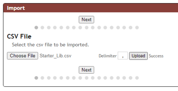
Step 6: Select Upload. When upload is complete, “Success” will be displayed next to the Upload button.
Step 7: Select Next.
Mapping Data Fields in OrCAD CIP
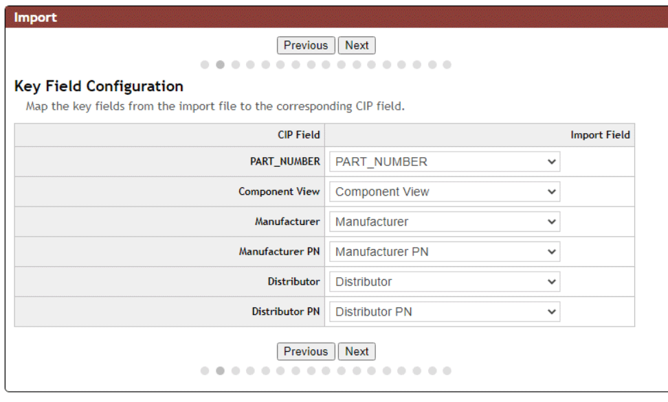
Step 8: In the Key Field Configuration, select the drop-down list for PART_NUMBER. Select PART_NUMBER as the field from the starter database file.
Step 9: Select the drop-down list for Component View and select Component View as the field from the starter database file.
Step 10: Select the drop-down list for Manufacturer and select Manufacturer as the field from the starter database file.
Step 11: Select the drop-down list for Manufacturer PN and select Manufacturer PN as the field from the starter database file.
Step 12: Select the drop-down list for Distributor and select Distributor as the field from the starter database file.
Step 13: Select the drop-down list for Distributor PN and select Distributor PN as the field from the starter database file.
Step 14: Select Next.
Automatically Mapping Database Fields
Note: Auto Map functionality will automatically map fields in the starter database to fields in CIP if the fields in the .csv file and CIP match. The included starter database has matching field names so the Auto Map feature can be used to quickly map the component database.
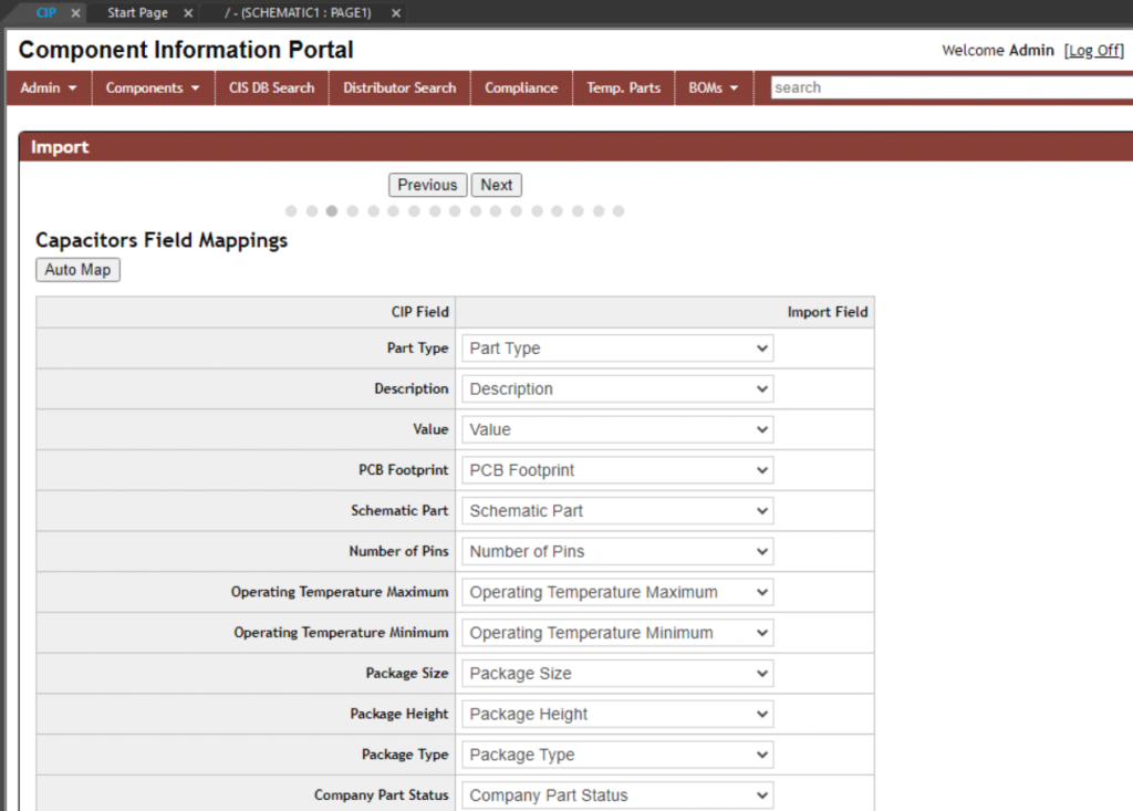
Step 15: In the Capacitors Field Mappings select Auto Map. The fields in the start database file are automatically mapped to the fields in CIP.
Step 16: Select Next.
Step 17: In the Connectors Field Mappings, select Auto Map. Select Next.
Step 18: In the Crystal and Oscillators Field Mappings, select Auto Map. Select Next.
Step 19: In the Diodes Field Mappings, select Auto Map. Select Next.
Step 20: In the ICs Field Mappings, select Auto Map. Select Next.
Step 21: In the Inductors Field Mappings, select Auto Map. Select Next.
Step 22: In the Mechanical Field Mappings, select Auto Map. Select Next.
Step 23: In the Misc Field Mappings, select Auto Map. Select Next.
Step 24: In the Relays Field Mappings, select Auto Map. Select Next.
Step 25: In the Resistors Field Mappings, select Auto Map. Select Next.
Step 26: In the Switches Field Mappings, select Auto Map. Select Next.
Step 27: In the Transformers Field Mappings, select Auto Map. Select Next.
Step 28: In the Transistors Field Mappings, select Auto Map. Select Next.
Step 29: In the Manufacturer Field Mappings, select Auto Map. Select Next.
Step 30: In the Distributor Field Mappings, select Auto Map. Select Save.
Import a Starter Database in OrCAD CIP
Step 31: In the Import window you can configure the desired options:
- Simulate: Check simulate to upload the database without changing any of the parts and component data. This will provide a preview of changes.
- Add Only: This will only Add new components to your component database.
- Add and Update: This will add new components to your database as well as update existing components.
Select Add Only.
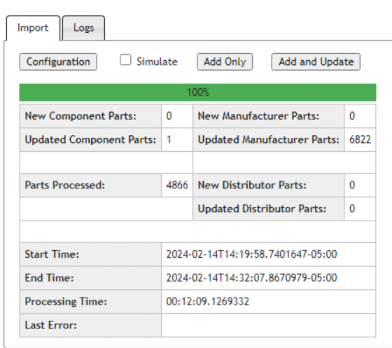
Step 32: The starter database will import, with the progress shown in the progress bar. When complete, the progress bar will display 100% and all import information will be visible.
Verifying the Starter Database Import
Step 33: Select Components > All from the CIP menu.
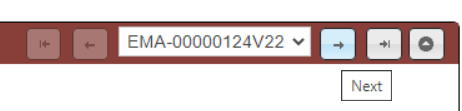
Step 34: View the component information displayed. Components can be navigated by using the arrows at the top of the window.
Step 35: Select Place to place the component in the schematic.
Step 36: Click to place the component in the schematic. Right click and select End Mode or Escape on the keyboard when finished.
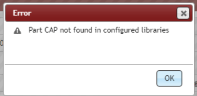
Note: If you receive an error that the part cannot be placed, continue to the INI File Configuration section below.
INI File Configuration
Note: If the component was placed successfully in OrCAD Capture, continue to Wrap Up & Next Steps.
Step 37: Locate your Capture.ini file on your computer. If you don’t know where the Capture.ini file is located, select View > Session Log Window from the OrCAD Capture menu and identify the path to the Capture.ini file.
Step 38: Navigate to and open the Capture.ini file in notepad or the text editor of choice.
Step 39: View the Part Management section of the Capture.ini file. If not configured, add the following text:
[Part Management]
Configuration File=\\<SERVER NAME>\CIP-E\Configuration_Files\<NAME OF DBCFILE>
TABLES OPTION=TABLE,VIEW
Note: The following information should be replaced with your specific configuration:
<SERVER NAME>: The name of the server configured for your component database. This is the server where the symbols, footprints, and database configuration file are stored.
<NAME OF DBC FILE>: Name of the desired database configuration file. There are several database configuration files provided with the CIP install depending on your desired configuration:
- CIP-E V7.7 CIS DB.DBC: Out-of-the-box settings for CIP that contains distributor part information in the manufacturer display.
- CIP-E V7.7 CIS DB_NODISTRIB.DBC: Out-of-the-box settings for CIP that does not contain distributor part information in the manufacturer display.
- CIP-E V7.7 CIS DB_WITHCOMPLIANCE.DBC: Out-of-the-box settings for CIP with Compliance Module enabled.
- CIP-E V7.7 CIS DB_NORELATIONAL.DBC: Out-of-the-box settings for CIP without any relational table settings.
- CIP-E V7.7 CIS DB_WITHCOMPLIANCE_NOSILICONEXPERTPNS.DBC: Out-of-the-box settings for CIP with Compliance Module enabled without SiliconExpert Part Numbers.
Step 40: View the Allegro Footprints section of the Capture.ini file. If not configured, add the following text:
[Allegro Footprints]
Dir0=\\<SERVER NAME>\CIP-E\Starter_Library\Allegro_Library\symbols
Note: The following information should be configured with your specific configuration:
<SERVER NAME>: The name of the server configured for your component database. This is the server where the symbols, footprints, and database configuration file are stored.
If there are existing paths for Allegro footprints, increment the Directory number as required (DIR1, DIR2, DIR3, etc.)
Step 41: View the Part Library Directories section of the Capture.ini file. If not configured, add the following text:
[Part Library Directories]
Dir0=\\<SERVER NAME>\CIP-E\Starter_Library\Schematic_Symbols
Note: The following information should be configured with your specific configuration:
<SERVER NAME>: The name of the server configured for your component database. This is the server where the symbols, footprints, and database configuration file are stored.
If there are existing paths for Part Library Directories, increment the Directory number as required (DIR1, DIR2, DIR3, etc.)
Step 42: Save and close the Capture.ini file.
Step 43: Back in OrCAD CIP with the component information still visible, select Place.
Step 44: Click to place the component in the schematic. Right-click and select End Mode or use Escape on the keyboard when finished.
Wrap Up & Next Steps
Quickly import a starter database in OrCAD CIP to configure your part library and get your design team setup for success with OrCAD CIP. Get more step-by-step instructions for OrCAD CIP at EMA Academy.
