Ensuring the accuracy of the schematic before transferring the design to the PCB layout phase is crucial step in the PCB design process to guarantee a functional end design. Manually scanning the design for errors upon schematic completion can be time-consuming and error-prone and missing a mistake, such as an incorrect or incomplete net connection, can result in PCB respins, adhoc modifications, or scrapped boards. OrCAD Capture makes it easy to identify errors during schematic design by monitoring potential design violations in real-time with Online DRC checking.
This quick how-to will provide step-by-step instructions on how to identify design errors during schematic design with real-time DRC checking in OrCAD Capture.
To follow along, download the provided files above the table of contents.
How-To Video
 Open in New Window
Configuring Online DRC in OrCAD Capture
Step 1: Open the provided design in OrCAD Capture.
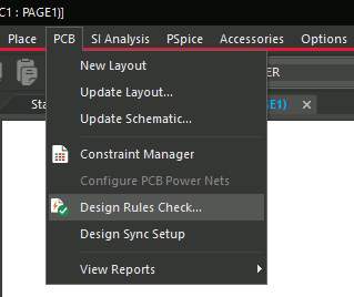
Step 2: Select PCB > Design Rules Check from the menu to activate the Design Rules Check window.
Note: In this window, you can configure settings for online and batch DRC checking. You can also configure the rules to check and how to report them.
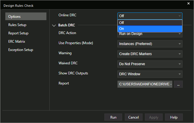
Step 3: Select On from the Online DRC drop-down menu. This will identify errors during schematic design in real-time.
Step 4: To configure the rules to check, select Rules Setup from the left side of the window.
Step 5: Under Electrical Rules, check Online for Check Single Node Nets and Check Unconnected Pins to enable live checking of these rules.
Step 6: Expand Physical Rules.
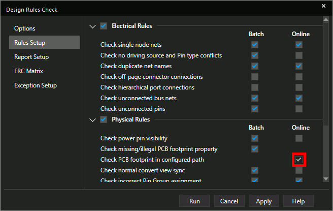
Step 7: Check Online for Check PCB Footprint in Configured Path. Click Apply and close the window.
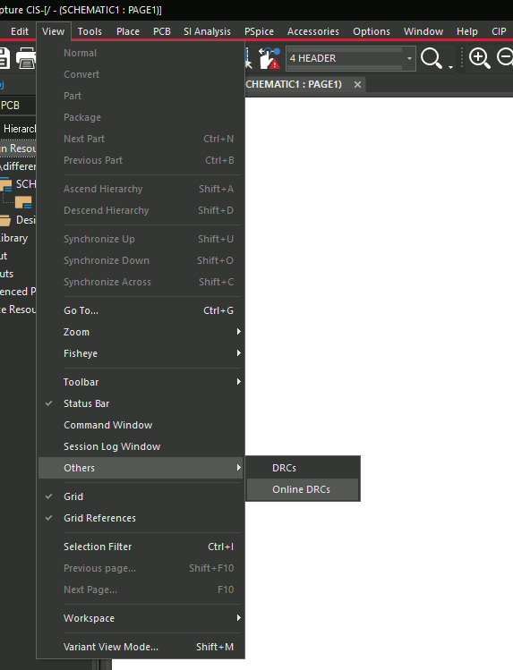
Step 8: To activate the online DRC panel, select View > Others > Online DRCs from the menu.
Identify Errors During Schematic Design with Online DRCs
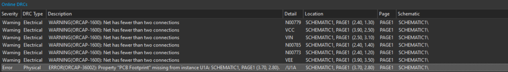
Step 9: View the Online DRC panel to identify errors during schematic design. An error has appeared for a missing PCB footprint for U1.
Step 10: To resolve the error, right-click U1 and select Edit Properties.
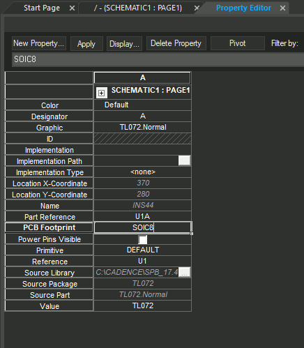
Step 11: The Property Editor tab opens. Select the cell for PCB Footprint and enter SOIC8.
Step 12: Click Apply and close the Property Editor tab.
Step 13: View the Online DRCs panel. The error has been automatically removed.
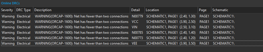
Note: Several warnings remain for nets with fewer than two connections.
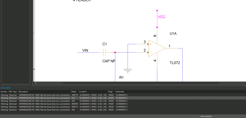
Step 14: Double-click one of the warnings to highlight the affected net on the schematic.
Note: These warnings can be resolved by connecting the unlabeled nets on J1 to the labeled nets on U1.
Step 15: Select Place > Net Alias from the menu or press N on the keyboard to open the Place Net Alias window.
Step 16: Enter VIN for the alias and click OK.
Step 17: Click to place the alias on the first pin of J1.
Step 18: Press N again to change the net alias. Enter VCC for the alias and click OK.
Step 19: Click to place the alias on pin 2 of J1.
Step 20: Press N to change the net alias. Enter VEE for the alias and click OK.
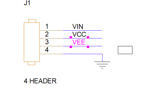
Step 21: Click to place the alias on pin 3 of J1. Press Escape on the keyboard when finished.
Step 22: View the Online DRCs panel. All errors and warnings have been cleared.
Wrap Up & Next Steps
Quickly identify errors during schematic design and resolve issues when change is easiest to guarantee the accuracy of your schematics in OrCAD Capture. Test out this feature and more with a free trial of OrCAD. Get access to free how-tos, courses, and walk-throughs at EMA Academy.
For a comprehensive check to identify errors during schematic design, learn how to configure a complete schematic design rule check here.


