Obtaining a realistic representation of your PCB design with 3D models is important to ensure proper fit and clearances in the PCB and product assemblies; however, generic 3D models may be inaccurate and creating custom 3D models reflecting your exact component specifications can be time consuming. With EDABuilder, you can automatically generate a 3D model or STEP model based on the exact specifications of your PCB footprint for accurate component modeling and analysis of your PCB design.
To view and generate a 3D model with EDABuilder, a 3D STEP viewer is required. There are many viewers available to preview a 3D STEP file. For this example, we will use IDA-STEP, which is free to download and use.
This quick how-to will provide step-by-step instructions on how to generate and view a 3D model with EDABuilder.
How-To Video
 Open in New Window
Installing a 3D STEP Viewer
Step 1: Click here to download IDA-STEP or install the desired 3D STEP viewer.
Note: If you are installing a different 3D STEP viewer, you can skip ahead to “Configure the 3D STEP Viewer in EDABuilder.”
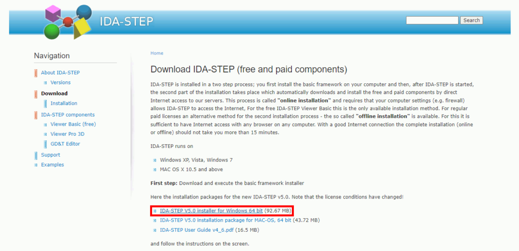
Step 2: Select IDA-STEP V5.0 Installer for Windows 64 or the desired IDA-STEP viewer to download the executable.
Step 3: Select Save As in your browser when prompted.
Step 4: Browse to a location to download the install package and click Save.
Note: Exact download procedure will vary by browser.
Step 5: In File Explorer, navigate to the location of the downloaded installer and run the installer. Follow all on-screen prompts.
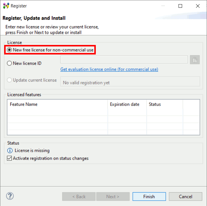
Step 6: IDA-STEP opens to the registration window. If you don’t have a license key, select New Free License and click Finish.
Step 7: Wait for the Update Manager to finish the installation. A prompt appears that the software needs to restart to complete licensing. Click OK.
Step 8: IDA-STEP is installed. Close the IDA-STEP window.
Configure the 3D STEP Viewer in EDABuilder
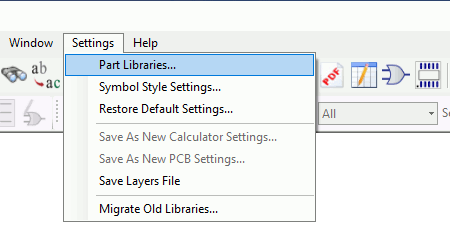
Step 9: Before a STEP file can be viewed in 3D via IDA-STEP in EDABuilder, IDA-STEP needs to be mapped as the STEP Part Browser. Open EDABuilder and select Settings > Part Libraries from the menu.
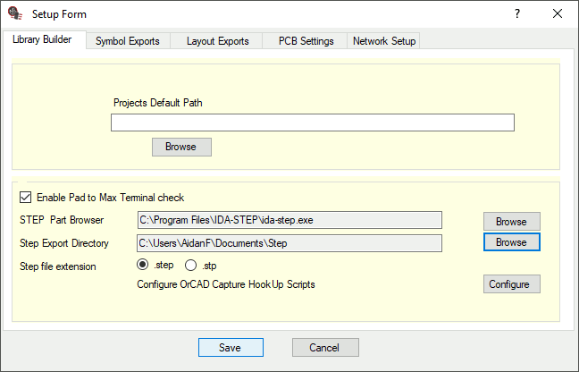
Step 10: The Setup Form window opens. Ensure the Library Builder tab is selected.
Step 11: Select Browse for STEP Part Browser.
Step 12: Browse to the location of the IDA-STEP executable: C:\Program Files\IDA-STEP. Select ida-step.exe and click Open.
Step 13: Select Browse for Step Export Directory.
Step 14: Browse to the working directory and click OK.
Note: Avoid using spaces in this file path.
Step 15: Click Save in the Setup Form window to save the settings and close the window.
Create a PCB Footprint with EDABuilder
Step 16: To generate a STEP Model, first a PCB footprint must be created. Select File > New > Footprint to create a footprint from a template.
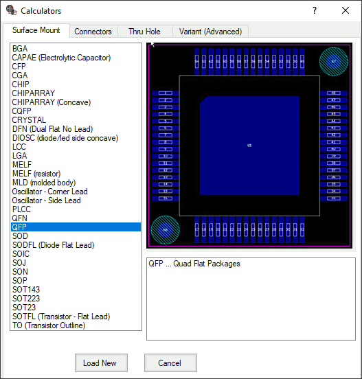
Step 17: The Calculators window opens with the available footprint templates. Select QFP from the list.
Step 18: Select Load New to create the new footprint.
Generate a 3D Model with EDABuilder
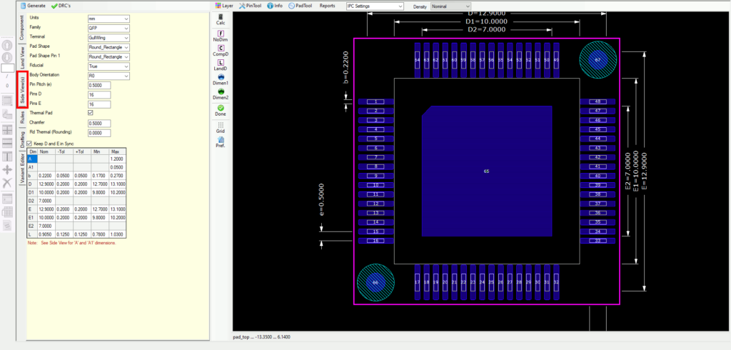
Step 19: A 2D render of the footprint is shown in the canvas. To open the 3D view, select the Side View(s) tab.
Step 20: A 2D side render of the footprint is shown. Select View STEP to open the 3D Step viewer.
Step 21: EDABuilder generates a 3D model based on the values defined in the PCB footprint. Click and drag with the left mouse button to pan the view.
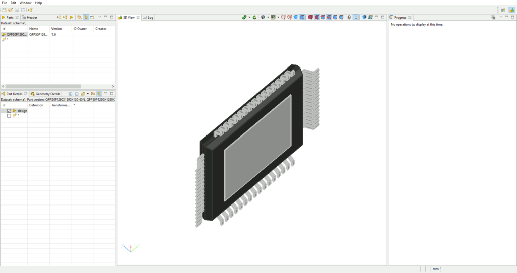
Note: If IDA-STEP opens to show a blank canvas, perform the following steps to load the generated file.
Step 1: Select Open from the IDA-STEP toolbar.
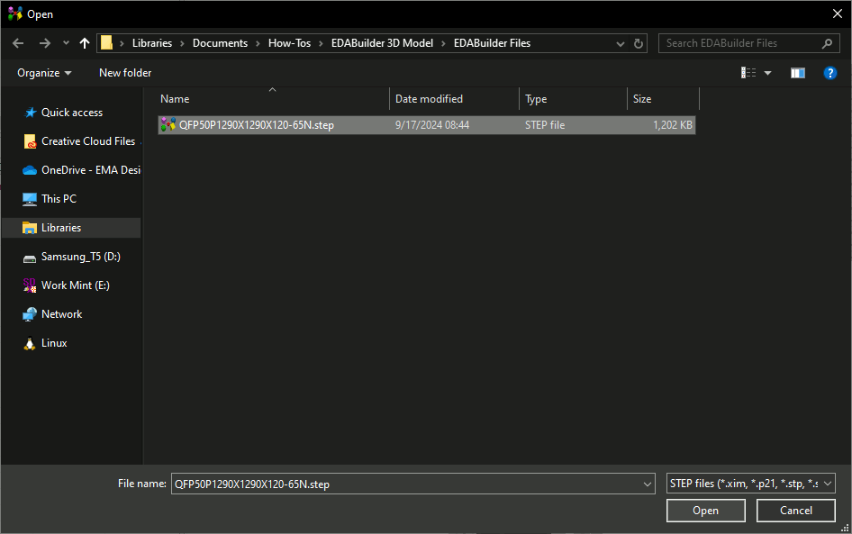
Step 2: Browse to the working directory. A STEP file is visible. Select the file and click Open.
Step 3: The STEP file is opened. Click and drag with the left mouse button to pan the view.
Step 22: Close IDA-STEP.
Modify the PCB Footprint and 3D Model
Note: If a footprint is modified in EDABuilder, the changes are automatically applied and EDABuilder generates a 3D model with the updated information.
Step 23: Back in EDABuilder, select the Component tab to reopen the 2D footprint view.
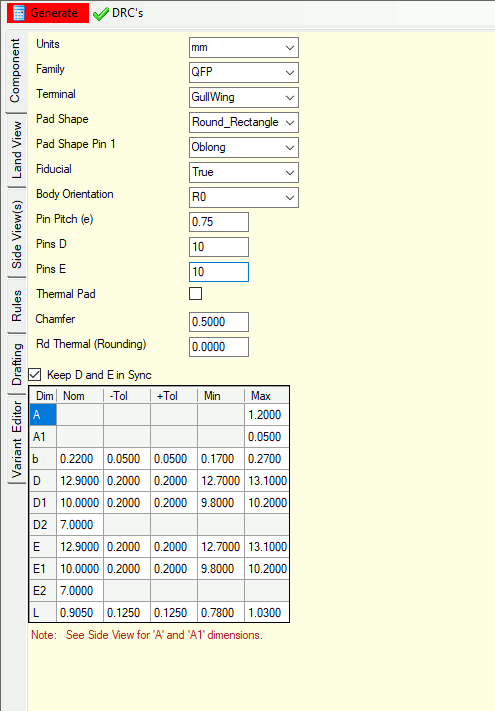
Step 24: Uncheck Thermal Pad to modify the footprint.
Step 25: Select Round_Rectangle for the Pad Shape and Oblong for the Pad Shape Pin 1.
Step 26: Enter 0.75 for the Pin Pitch.
Step 27: Enter 10 for Pins D and Pins E to create a QFP footprint with 10 pins on each side.
Step 28: Select Generate to regenerate the footprint with the defined settings and values.
Step 29: The footprint in the canvas is refreshed to reflect the changes defined. Select the Side View(s) tab. Select View STEP to open IDA-STEP.
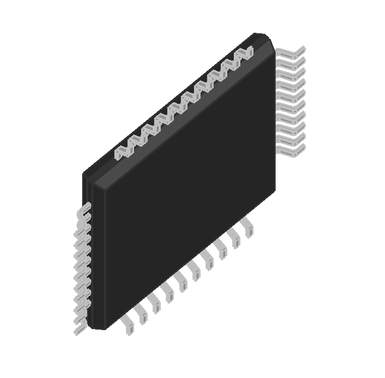
Step 30: EDABuilder will generate a 3D model with the updated values. The thermal pad has been removed and the pins are further apart.
Wrap Up & Next Steps
Efficiently generate a 3D model with EDABuilder to obtain a realistic representation of the components used in your PCB designs. Get more step-by-step instructions for EDABuilder at EMA Academy.

