A realistic simulation is often required to verify circuit behavior before PCB production. Extensive model libraries of generic components as well as manufacturer specific parts can help produce an accurate simulation; however, it can be overwhelming and difficult to find the correct part, especially if the exact part number is still unknown. With PSpice Part Search in PSpice Designer, easily browse the thousands of available parts or perform a search on the name and description to quickly find the desired models.
This how-to will provide step-by-step instructions for utilizing the PSpice Part Search to quickly build and simulate a buck converter circuit.
How-To Video

Creating a New PSpice Project
Step 1: Open OrCAD PSpice Designer.
Step 2: Select File > New > Project from the menu.
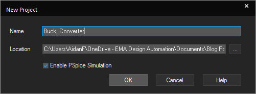
Step 3: Enter Buck_Converter as the name. Browse to the desired location to save the project. Make sure Enable PSpice Simulation is checked and click OK.
Step 4: Select Create a blank project and click OK.
Searching for a Voltage Source
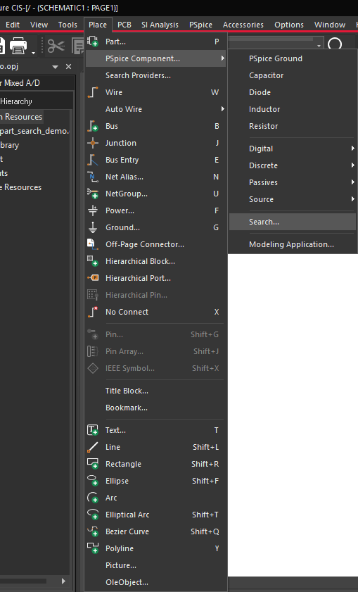
Step 5: Select Place > PSpice Component > Search from the menu.
Note: The PSpice Model Search can be used to place both generic components and vendor specific components.
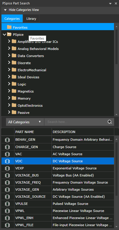
Step 6: Under the Categories tab, open PSpice > Source > Independent Sources > Voltage Source.
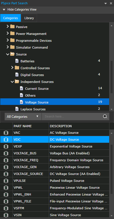
Step 7: Select VDC. Double-click to attach the part to the cursor.
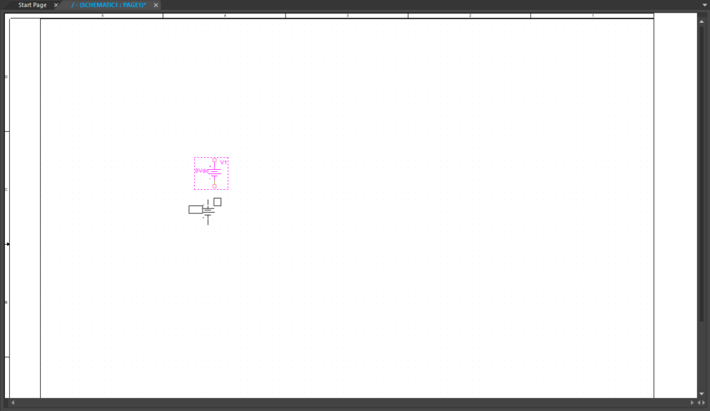
Step 8: Click in the schematic canvas to place the part. Right-click and select End Mode or press Escape on the keyboard.
Step 9: Double-click the component value, 0Vdc, to edit properties.
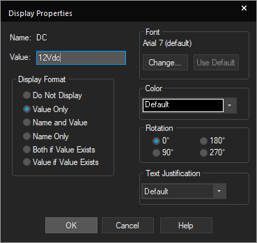
Step 10: Change the value to 12Vdc and click OK.
Searching for a PSpice Capacitor
Step 11: Back in the PSpice Part Search window, scroll up under the Categories tab and select Favorites.
Note: This will open a list of commonly used ideal components.
Step 12: Double-click L from the list to place an inductor. Click to place in the schematic.
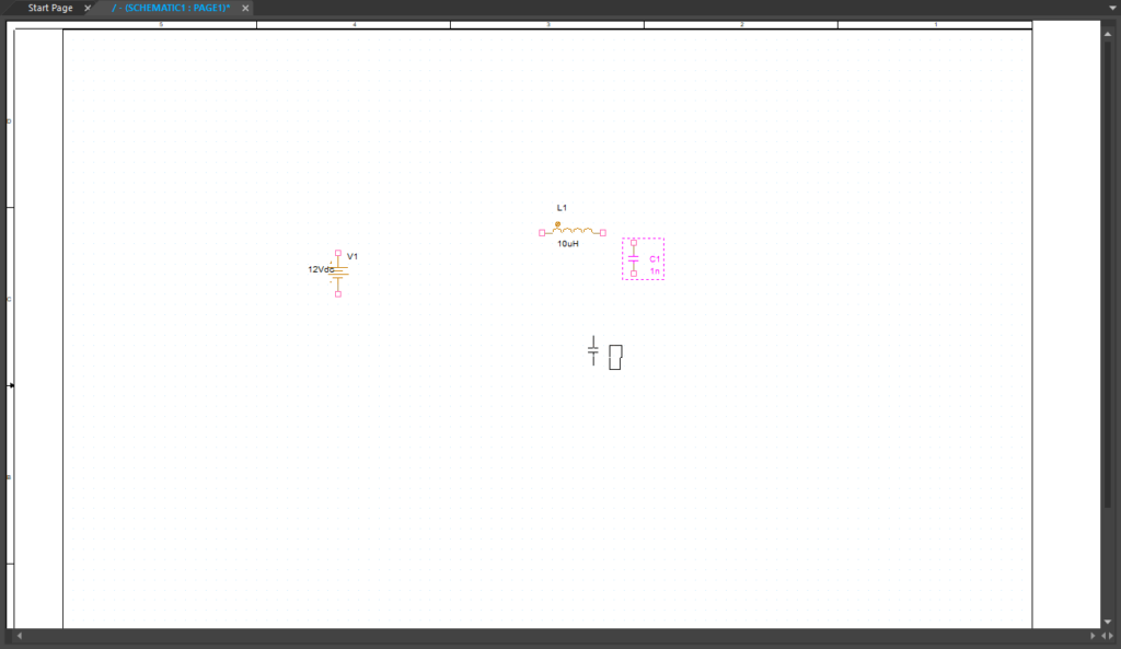
Step 13: Double-click C from the list to place a capacitor. Click to place in the schematic. Right-click and select End Mode (Escape).
Note: Use R on the keyboard to rotate components in 90-degree increments as needed.
Step 14: Double click on a component value. Change the inductor value to 100uH and the capacitor value to 100uF.
Searching for a PSpice Diode
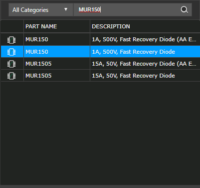
Step 15: In the PSpice Part Search, enter MUR150 into the search bar and press Enter on the keyboard.
Step 16: Double-click MUR150.
Note: If browsing, MUR150 can be found in the Categories tab, under PSpice > Discrete > Diodes.
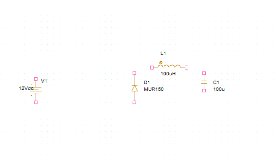
Step 17: Click to place as shown in the schematic. Right-click and select End Mode (Escape).
Step 18: In the PSpice Part Search, enter 8A 500V MOSFET into the search bar to search for a description. Press Enter.
Searching for a PSpice MOSFET
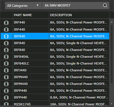
Step 19: Scroll down and double-click the part with name IRF840.
Note: If browsing, this component can be found under PSpice > Discrete > MOSFET > Power MOSFET > N Channel.
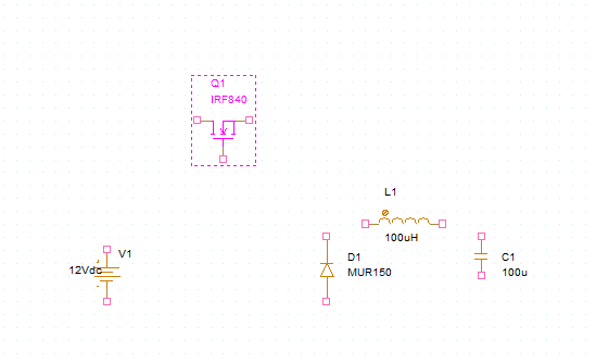
Step 20: Click to place in the schematic. Right-click and select End Mode (Escape).
Placing PSpice Ground
Step 21: Select Place > PSpice Component > PSpice Ground from the menu.
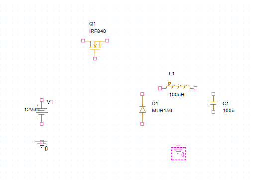
Step 22: Click to place the grounds in the schematic. Right-click and select End Mode (Escape).
Placing PSpice Resistors
Step 23: Select Place > PSpice Component > Resistor from the menu.

Step 24: Click to place a load resistor at the output of the buck converter.
Step 25: Click to place another resistor at the gate of the MOSFET. Right-click and select End Mode (Escape).
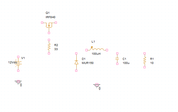
Step 26: Double click the component value to edit. Set the value of the load resistor to 10 ohms and the gate resistor value to 33 ohms.
Step 27: Close out of the PSpice Part Search window.
Wiring a PSpice Circuit
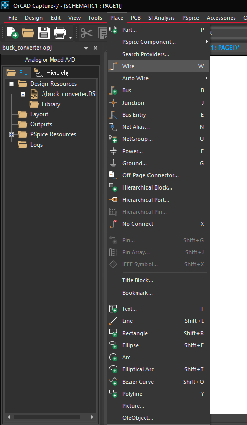
Step 28: Select Place > Wire from the menu, the Wire button on the toolbar, or press W on the keyboard.
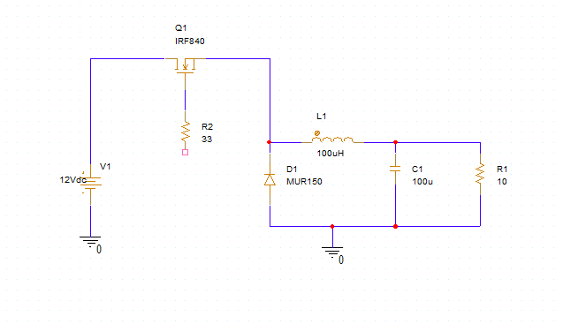
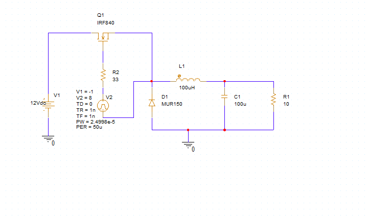
Step 29: Click to wire the schematic. When finished, press the Escape key on the keyboard.
Creating a PSpice Pulse Source
Step 30: Select Place > PSpice Component > Modeling Application from the menu.
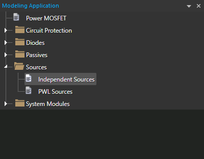
Step 31: Choose Sources > Independent Sources from the Modeling Application.
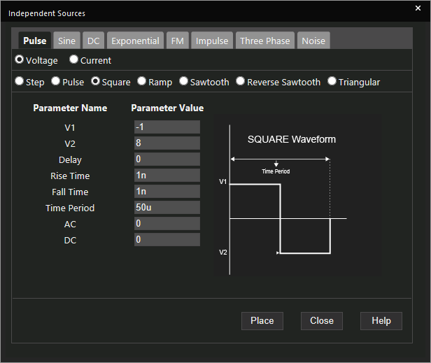
Step 32: In the Independent Sources window, select Square under the Pulse tab.
Step 33: Set the following parameters for the pulse:
- V1: -1
- V2: 8
- Rise Time: 1n
- Fall Time: 1n
- Time Period: 50u
Step 34: Select Place.
Step 35: Click to place the source.
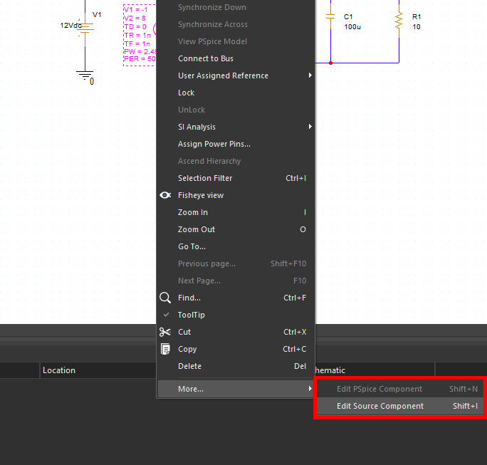
Note: If any source values need to be modified, select the source, right-click and select More > Edit Source Component.
Step 36: Select Place > Wire (W) from the menu and click to wire the source. Press Escape on the keyboard when finished.
Creating a Transient Simulation
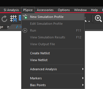
Step 37: Select PSpice > New Simulation Profile from the menu.
Step 38: Name the simulation BUCK_CONVERTER_TRANS and click Create.
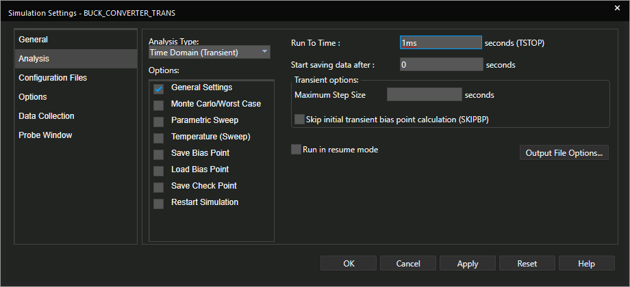
Step 39: Set the Run To Time to 1ms. Leave all other settings as the defaults and click OK.
Performing a Transient Simulation
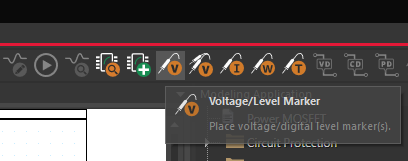
Step 40: Select the Voltage Level/Marker button from the toolbar.
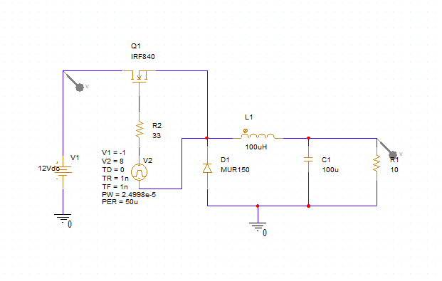
Step 41: Place a probe at the input and another at the output. Right-click and select End Mode when finished or press Escape on the keyboard.
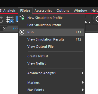
Step 42: Select PSpice > Run from the menu or the Run button on the toolbar.
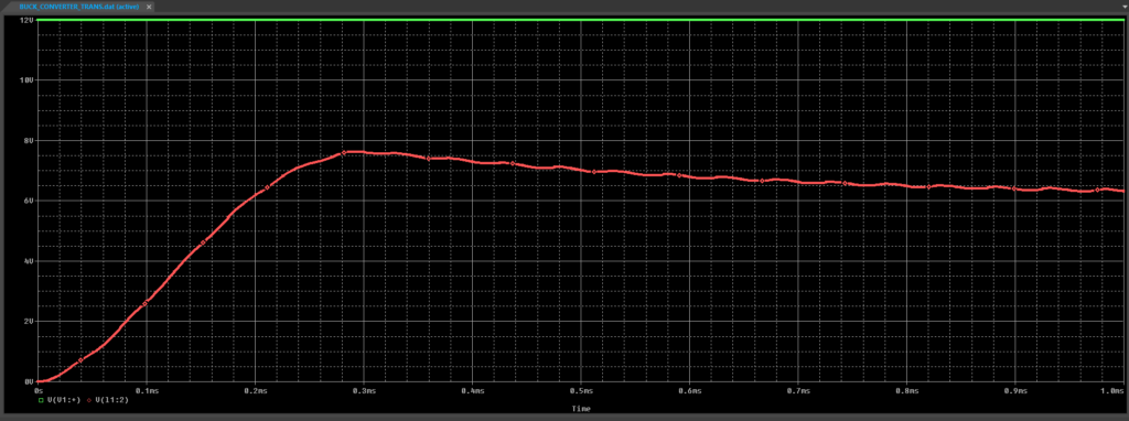
Step 43: View the simulation results.
Wrap up & Next Steps
Quickly create and simulate circuitry with efficient navigation of the expansive model libraries through browsing and searching with PSpice Part Search in OrCAD. Learn more about PSpice and get your free trial of OrCAD.

