Ensuring that a PCB is error-free before putting the board into production is a crucial step in the PCB design process to guarantee a functional end design. Most boards, especially complex high-speed designs, have very little margin for error. Constraints must be used to ensure design functionality. With OrCAD X Presto, you can easily find DRC errors or constraint violations in your design to quickly identify and correct errors.
This quick how-to will provide step-by-step instructions on how find DRC errors in OrCAD X Presto.
To follow along, download the provided files above the table of contents.
How-To Video
 Open in New Window
Opening the DRC Browser
Step 1: Open the provided design in OrCAD X Presto.
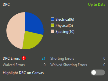
Step 2: View the DRC subpanel under Status in the Properties panel. The DRC count is listed as a hyperlink and the types of errors present are shown in a pie chart.
Note: If the Properties panel is not open, select View > Panels > Properties from the menu.
Find DRC Errors in OrCAD X Presto for Spacing Constraints
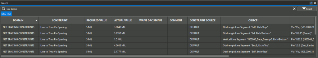
Step 3: Select the Spacing portion of the pie chart. The Search panel automatically opens to show the spacing errors.
Note: Select Auto Hide in the Search panel to keep the panel on screen.
Step 4: The pie chart is updated to show the types of spacing errors present. Select Line To.
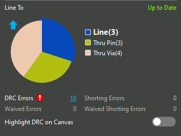
Step 5: The pie chart updates to show the types of Line To spacing errors present. Select Line to list the Line-to-Line errors.
Note: Select the Up arrow to return to the previous level of specificity.
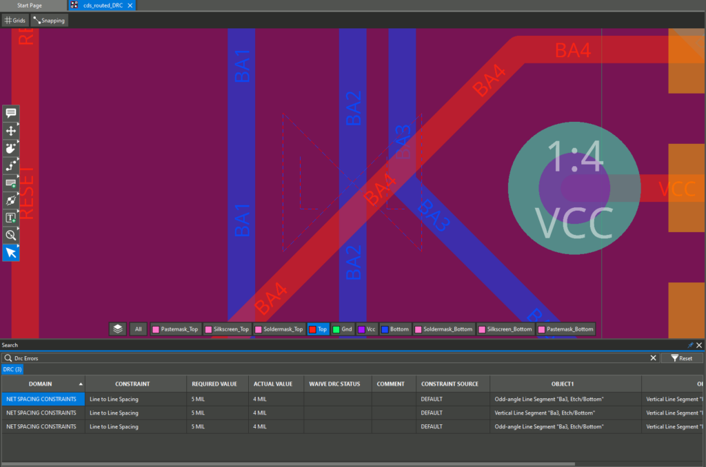
Step 6: Violations of Line-to-Line spacing constraints are shown in the Search panel. Double-click an error to be brought to its location on the board.
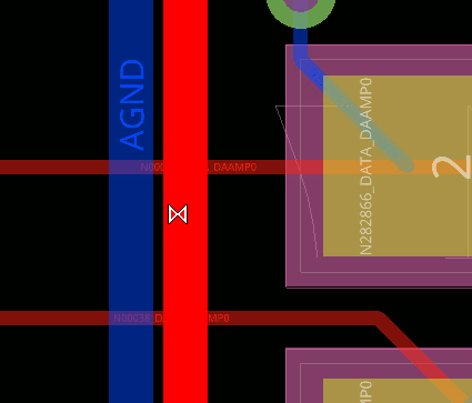
Step 7: View the PCB canvas. A DRC marker identifies where the violations occur. Hover over the DRC error to view additional information.
Step 8: To correct spacing errors, select the Slide mode from the toolbar.
Step 9: Click a trace to attach it to your cursor. Move your mouse to slide the trace and increase the spacing between its neighbors. Click again to place the trace.
Note: If the trace turns red and a DRC symbol appears, placing the trace in that position will result in a DRC error.
Step 10: Repeat this process as needed to correct the line-to-line spacing errors. When the list has been cleared, the pie chart will return to the uppermost level.
Step 11: Press Escape on the keyboard to return to the Select mode when finished or select the Arrow icon on the toolbar.
Find DRC Errors in OrCAD X Presto for Physical Constraints
Step 12: Select Physical in the DRC pie chart.
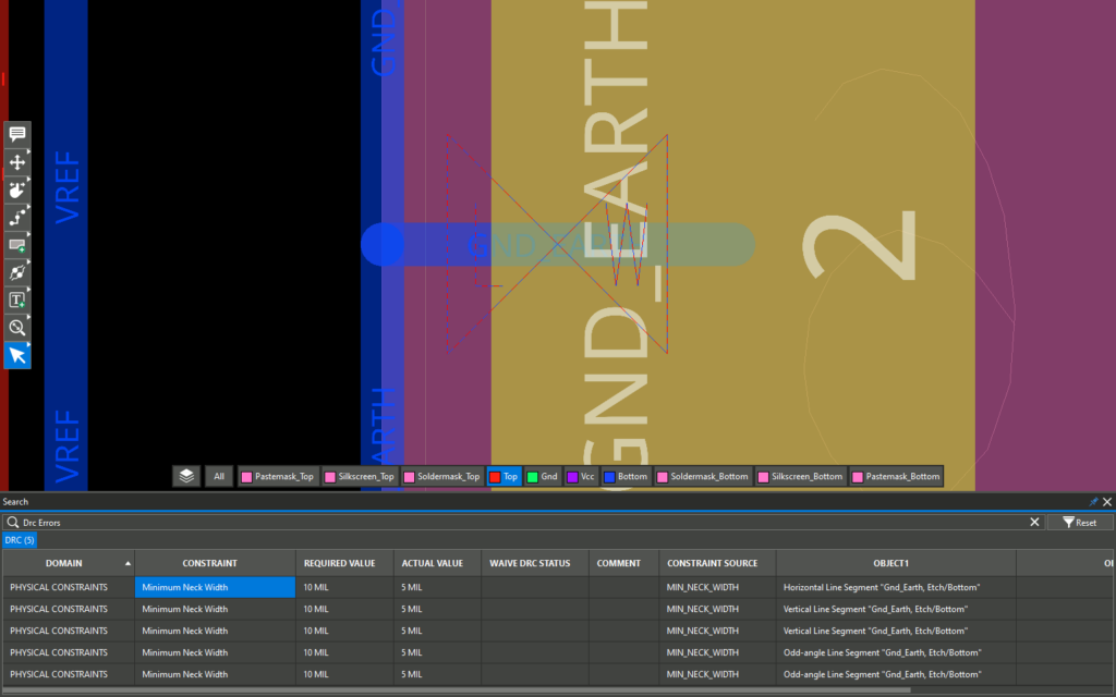
Step 13: The pie chart is updated to show the types of physical constraint violations present. Only Minimum Neck Width violations are shown for this board. Select Auto Hide to prevent the panel from closing.
Step 14: Double-click a violation in the Search panel to be brought to its location.
Step 15: Select the trace with the DRC error in the PCB canvas.
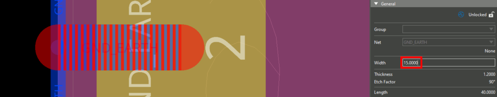
Step 16: In the Properties panel, change the line width to 15 mils.
Step 17: Repeat steps 14 through 17 to correct the Minimum Neck Width Violations.
Note: Line width can also be corrected directly in the Search Panel- learn how here.
Find DRC Errors in OrCAD X Presto for Electrical Constraints
Step 18: Select Electrical in the pie chart in the Properties panel.
Step 19: The sub-chart is divided into two sections, Differential Pair Maximum Uncoupled Length and Differential Pair Phase Tolerance, and the Search panel lists all electrical violations. Hover over the Constraint column header and select the Filter symbol to filter by constraint type.
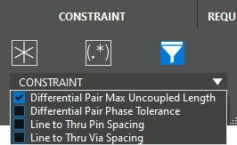
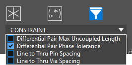
Step 20: Select the Filter List option and check Differential Pair Max Uncoupled Length from the filter drop-down. Click OK.
Note: To learn more about assigning and correcting constraints for differential pairs and other critical rules for PCB designs view our free course: Constraints for Every Design.
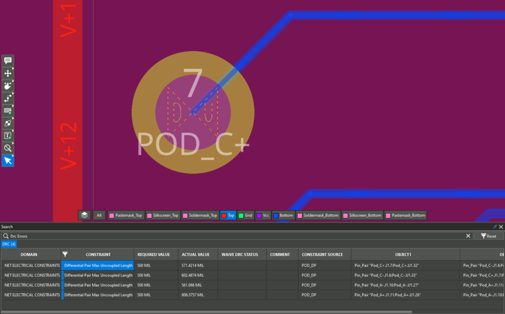
Step 21: All Differential Pair Max Uncoupled Length violations are listed. Double-click a violation to be brought to its location.
Step 22: Select the Filter symbol in the column header.
Step 23: In the filter drop-down, uncheck Differential Pair Max Uncoupled Length and check Differential Pair Phase Tolerance.
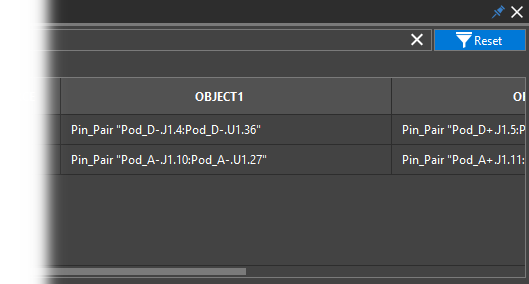
Step 24: Click OK. A new constraint list is generated.
Step 25: Select Reset in the Search panel to clear the filters.
Wrap Up & Next Steps
Quickly find DRC errors in OrCAD X Presto using the properties panel and search panel to efficiently correct constraint violations and achieve first-pass design success with OrCAD X Presto. Don’t have OrCAD X Presto? Get your free trial and for more step-by step instructions and walk-throughs on using OrCAD X Presto visit EMA Academy.

