With today’s designs and enclosures becoming more compact, board space is at a premium for most new devices. While components have also become more compact, if a device enclosure has more height than length or width, incorporating rigid flex can significantly reduce the footprint of the board and allow for smaller sections to fit into tighter spaces. These rigid-flex designs require multiple stackups and zones which must be managed efficiently to produce the board correctly. OrCAD X Presto allows you to quickly create zones for rigid-flex designs and define the stackup and constraints associated with zones for efficient management.
This quick how-to will provide step-by-step instructions on how to create zones for rigid-flex designs to assign stackups and constraints to sections of the PCB in OrCAD X Presto.
To follow along, download the provided files above the table of contents.
How-To Video
 Open in New Window
Create Zones for Rigid-Flex Designs: Flex
Step 1: Open the provided design in OrCAD X Presto.
Note: Before zones can be defined, the zone stackups must be defined in the Cross-Section Editor. Learn how to configure multiple stackups in the PCB design here.
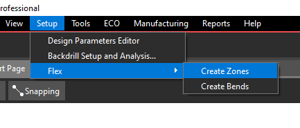
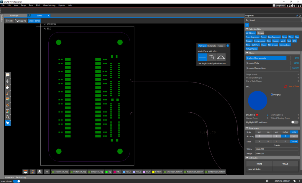
Step 2: To create a zone on the board, select Setup > Flex > Create Zones from the menu.
Step 3: Select Rectangle in the zone creation widget.
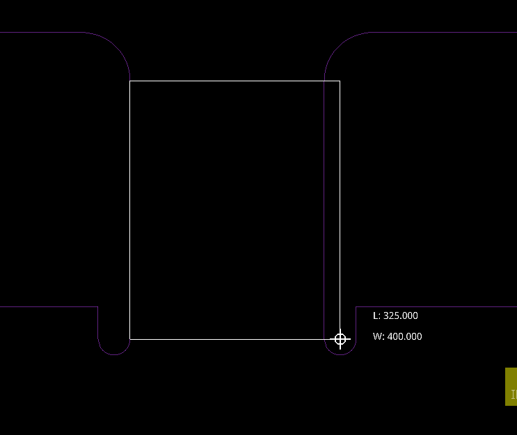
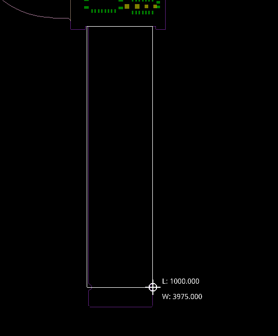
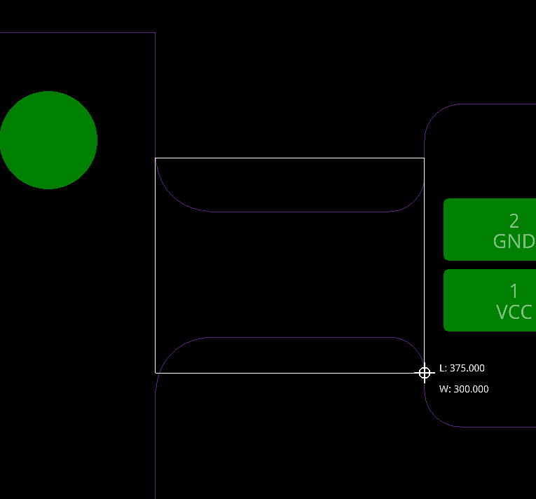
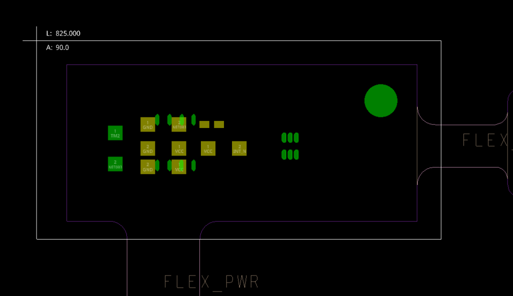
Step 4: Click the start of the first flex area to start drawing a zone. Move the mouse to the end and click again to finish. The zone will automatically snap to the board outline.
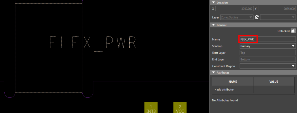
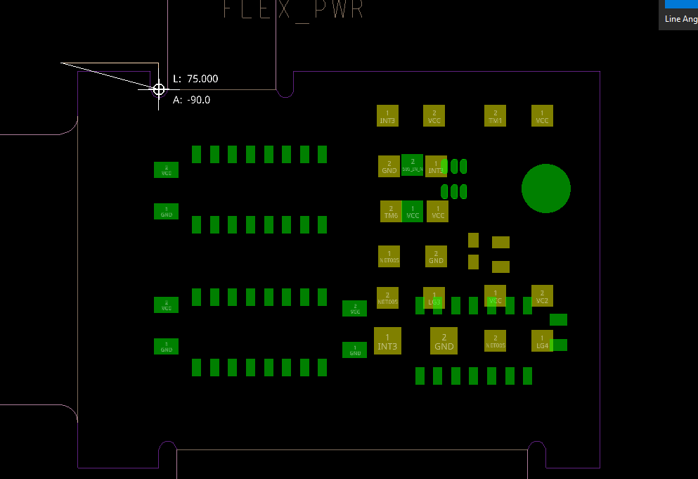
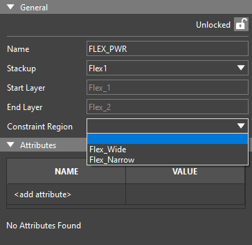
Step 5: The Properties panel automatically displays flex zone properties. The name is automatically defined as ZONE_1. Enter Flex_PWR for the name. The name is updated on the PCB canvas.
Step 6: Define the stackup for the zone. Select Flex1 from the Stackup drop-down menu.
Note: The Start Layer and End Layer are filled in automatically.
Step 7: Define the constraints used in the zone. Select Flex_Narrow from the Constraint Region drop-down menu.
Step 8: Select Lock to lock the zone.
Step 9: Click the start of the second flex area to start drawing a zone, move the mouse to the end, and click again to finish.
Step 10: In the Properties panel, enter Flex_LCD for the zone name,select Flex2 from the Stackup dropdown, and select Flex_Wide from the Constraint Region dropdown. Select Lock to lock the zone.
Step 11: Click the start of the third zone, move the mouse to the end, and click again to finish.
Step 12: In the Properties panel, enter Flex_CN for the zone name,select Flex3 from the Stackup dropdown, and select Flex_Wide from the Constraint Region dropdown. Select Lock to lock the zone.
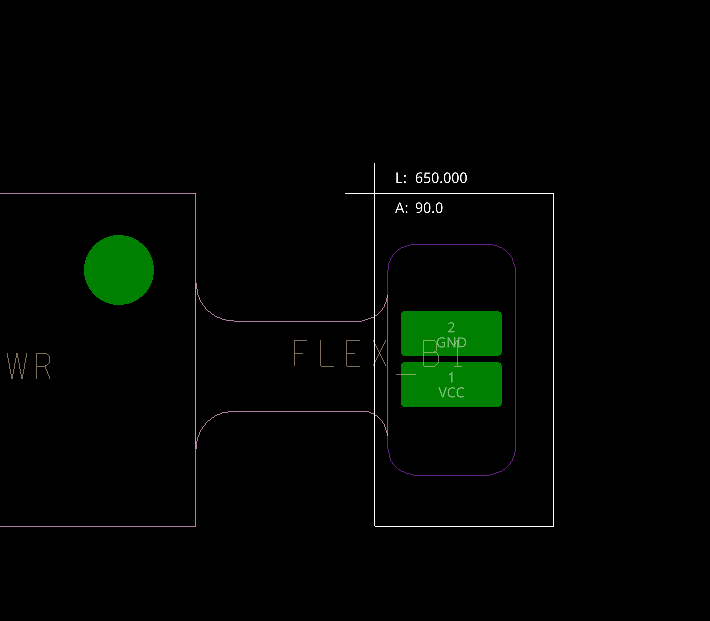
Step 13: Click the start of the last zone, move the mouse to the end, and click again to finish.
Step 14: In the Properties panel, enter Flex_B1 for the zone name, select Flex1 from the Stackup dropdown, and select Flex_Narrow from the Constraint Region dropdown. Select Lock to lock the zone.
Create Zones for Rigid-Flex Designs: Rigid
Step 15: Select Polygon in the zone creation widget.
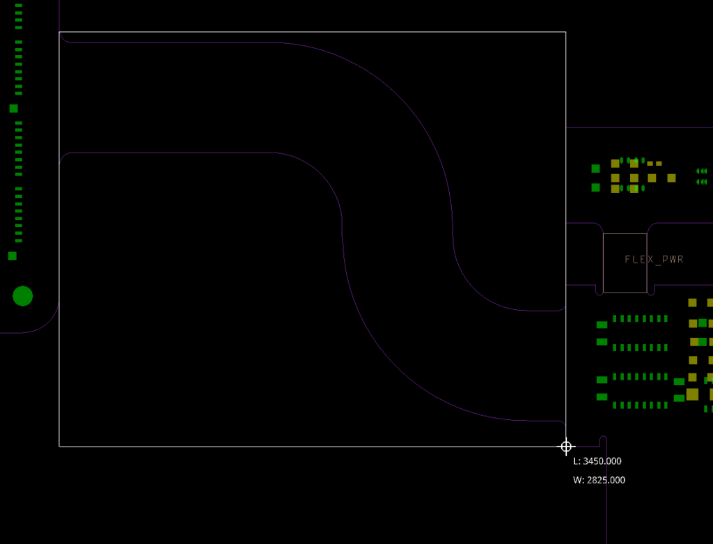
Step 16: Click to start drawing a polygon around the main PCB area.
Step 17: Click around the main to draw the polygon zone. Click the start of the shape to close it and create the zone.
Step 18: In the Properties panel, enter BOARD_MAIN for the zone name.
Note: Primary is automatically selected as the stackup, as required for rigid zones.
Step 19: Click to start drawing a polygon around the LED display PCB area. Click the start of the shape to close it and create the zone.
Step 20: In the Properties panel, enter BOARD_DISP for the zone name.
Step 21: Click to start drawing a polygon around the power PCB area and click the start of the shape to finish.
Step 22: In the Properties panel, enter BOARD_PWR for the zone name.
Step 23: Click to start drawing a polygon around the battery connector PCB area and click the start of the shape to finish.
Step 24: In the Properties panel, enter BOARD_BATT for the zone name.
Step 25: Click the Select mode in the toolbar to disable the zone creation mode.
Previewing the Rigid Flex in 3D
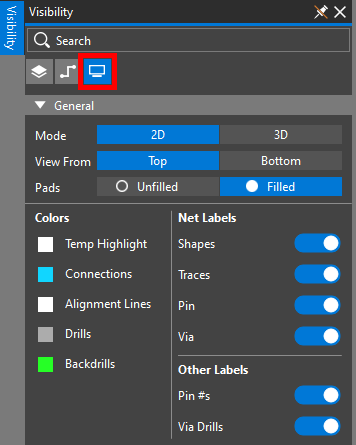
Step 26: Rigid flex zones are clearly indicated in the 3D view. To activate the 3D view, open the Visibility panel and select the Display mode.
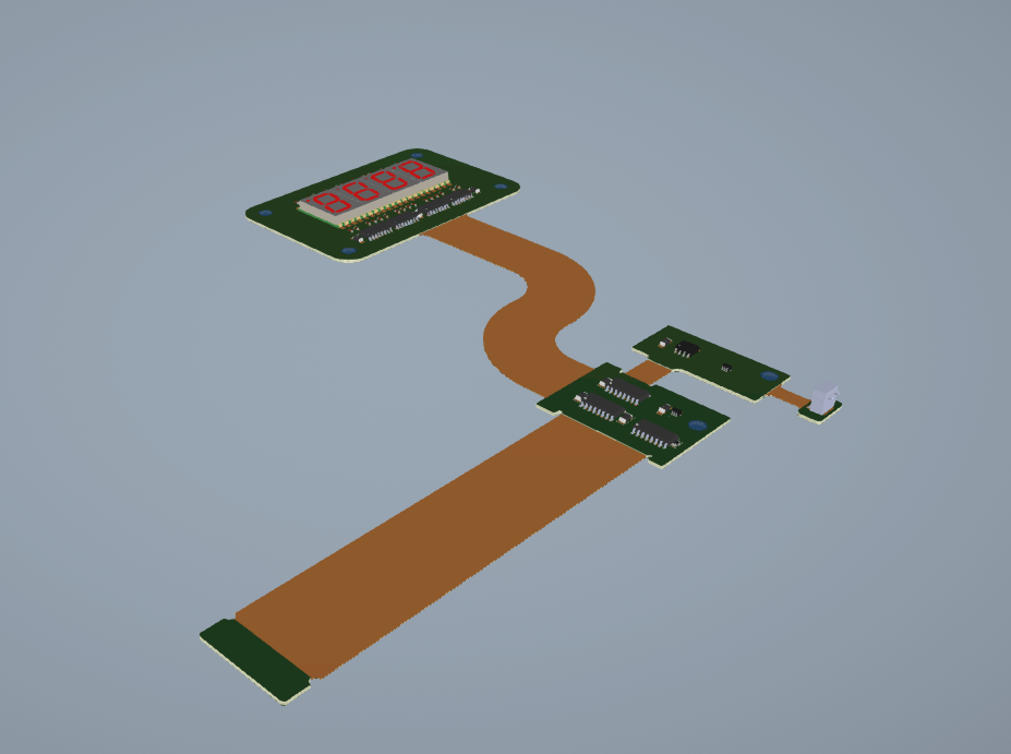
Step 27: Select 3D. The 3D canvas is activated, showing the assigned rigid-flex zones.
Note: Bends can be added to rigid flex zones to determine 3D fitment more accurately. To learn more about adding bends to a rigid flex design, see our how-to here.
Managing Zones for Rigid-Flex Designs
Step 28: Select 2D to return to the 2D board view.
Step 29: Select the FLEX_PWR zone. The Properties panel is populated with zone properties.
Step 30: Select Unlock and choose the empty space from the Constraint Region dropdown. This will remove the region-specific constraint set and apply the default constraint set to this zone.
Wrap Up & Next Steps
Quickly and efficiently create zones for rigid-flex designs and manage the required stackups and constraints for your complex PCBs in OrCAD X Presto. Test out this feature and more with a free trial of OrCAD. For more how-tos and step-by-step walk-throughs, visit EMA Academy.
