Analyzing circuit behavior is a critical step in the PCB design process to ensure functionality once the board is produced. In order to produce a realistic SPICE simulation, accurate models are required. PSpice contains multiple methods to obtain a realistic circuit analysis with:
- An extensive model library
- A wizard-based approach to model creation
- Import wizards to create SPICE models from manufacturer-provided data
This quick how-to will provide step-by-step instructions on how to create SPICE models in PSpice.
To follow along, download the provided files above the table of contents.
How-To Video
 Open in New Window
Model Libraries in PSpice
Step 1: Open the provided design in OrCAD PSpice Designer.
Step 2: Select Place > Component from the menu.
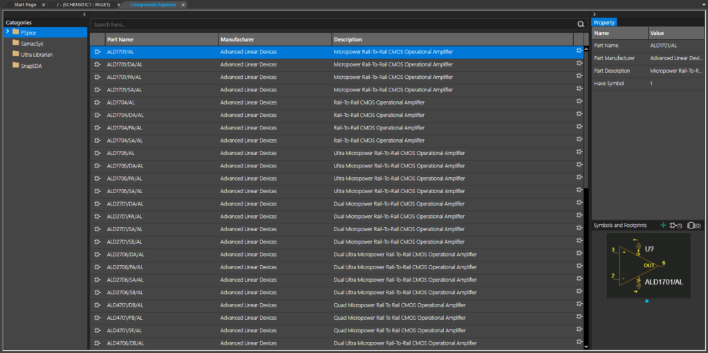
Step 3: The Component Explorer tab opens. Select PSpice from the Categories list.
Note: This category lists all included PSpice models. To place a model, select it, right-click and select Place.
Step 4: Expand the PSpice category and select Discrete. Here you can view all discrete component models available such as transistors, diodes, and MOSFETs.
Note: Other types of components are available, such as variable capacitors, realistic inductors, analog behavioral models, and more.
Step 5: Close the Component Explorer tab.
Create SPICE Models
Note: Include in PSpice is the Modeling Application which provides a wizard-based approach to creating custom SPICE Models. Multiple types of models are available including sources, Zener diodes, and switches.
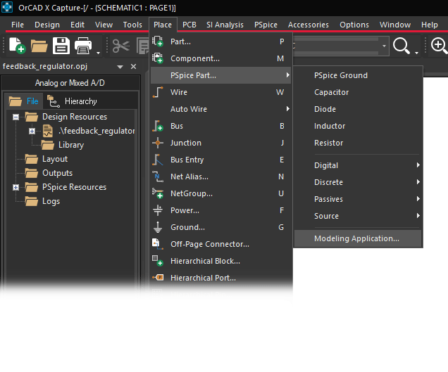
Step 6: Select Place > PSpice Part > Modeling Application from the menu.
Step 7: Select Power MOSFET to create and place a MOSFET model. The Power MOSFET window opens.
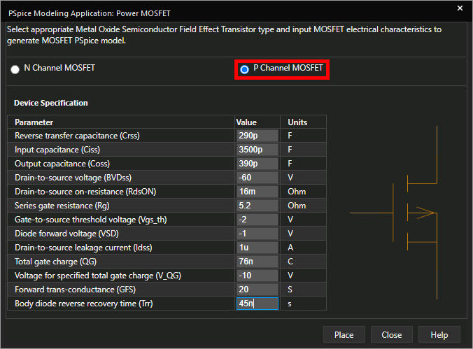
Step 8: Select P Channel MOSFET from the top of the window.
Step 9: Enter the following parameter values:
- Reverse Transfer Capacitance: 290p
- Input Capacitance: 3500p
- Output Capacitance: 390p
- Drain-to-Source Voltage: -60
- Drain-to-Source On-Resistance: 16m
- Series Gate Resistance: 5.2
- Gate Source Threshold Voltage: -2
- Diode Forward Voltage: -1
- Drain-to-Source Leakage Current: 1u
- Total Gate Charge: 76n
- Voltage Specified for Total Gate Charge: -10
- Forward Transconductance: 20
- Body Diode Reverse Recovery Time: 45n
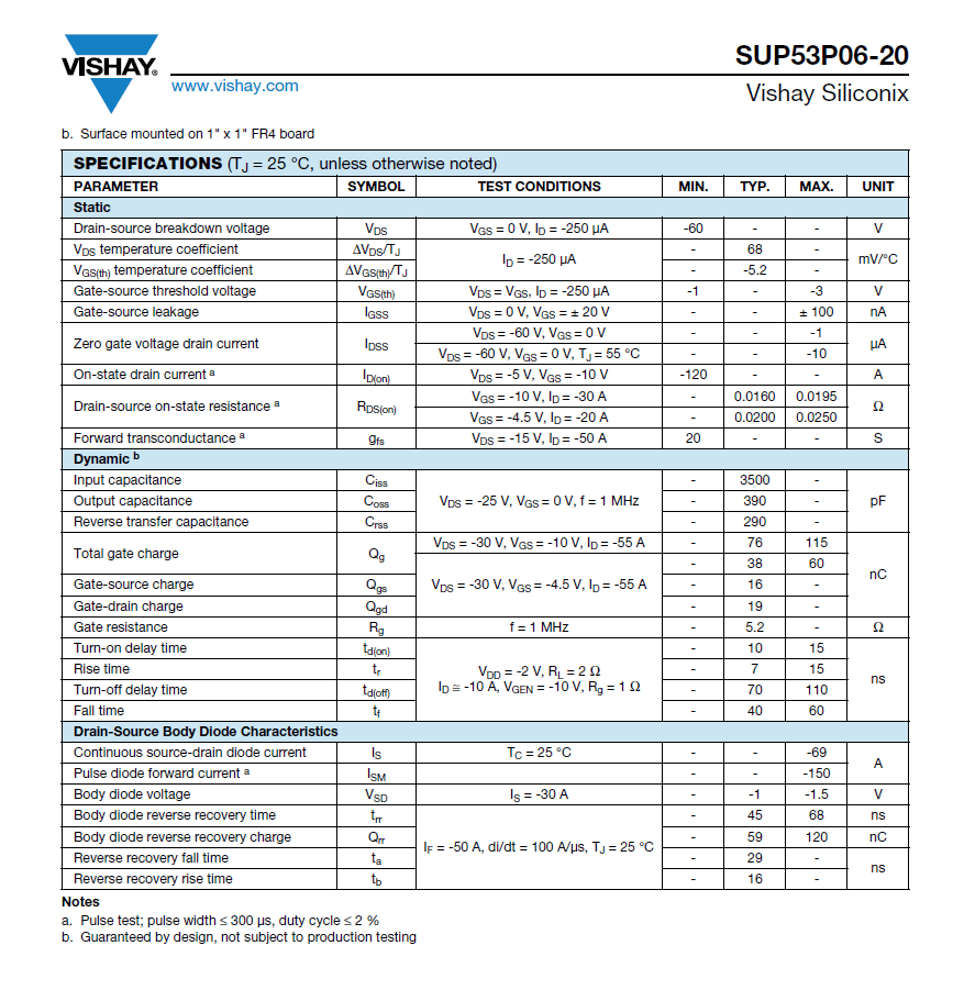
Note: These values are specific to the Vishay SUP53P06-20 power MOSFET. The values can be obtained from its datasheet, included with the provided materials. Using values provided by the manufacturer will create SPICE models for simulation with realistic operation and performance.
Step 10: Click Place to place the component.
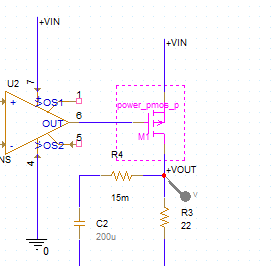
Step 11: Click to place the MOSFET in the empty space as shown.
Note: Use V on the keyboard to flip the component vertically.
Running the Simulation
Step 12: Select PSpice > Run from the menu.
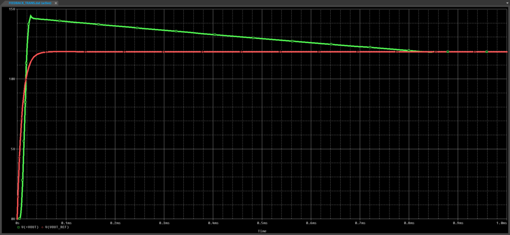
Step 13: View the simulation results. The reference voltage rises to 12V and the output rises briefly above 12V before decaying and ramping down.
Step 14: Close the PSpice A/D window.
Loading a SPICE Model
Note: Manufacturers sometimes provide SPICE models for components. Create SPICE models in PSpice by loading these models from 3rd-party sources.
Step 15: Select the ground symbol on the anode of D1 and press Delete on the keyboard.
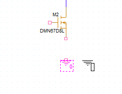
Step 16: Select Place > PSpice Part > Discrete > NMOS from the menu.
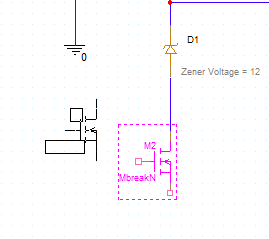
Step 17: Click to place the MOSFET in the circuit. Right-click and select End Mode when finished.
Step 18: Right-click the MOSFET and select Associate PSpice Model.
Step 19: A prompt will appear that attaching a new implementation will override the existing implementation. Click Yes to accept.
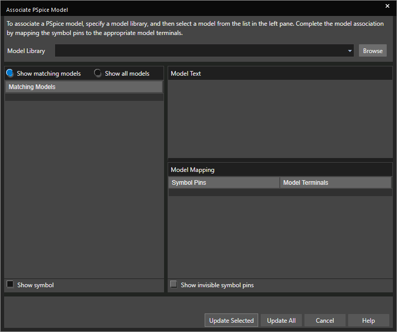
Step 20: The Associate PSpice Model window opens. Select Browse to browse for a SPICE model.
Step 21: Browse to the provided files and select DMN67D8LW.lib. Click Open.
Note: This SPICE model is available for download from Diodes Incorporated.
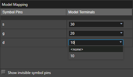
Step 22: Under Model Mapping, assign the following model terminals to the symbol pins:
- S: 30
- G: 20
- D: 10
Note: View the .lib file in a text editor or the PSpice Model Editor to confirm pin names.
Step 23: Click Update Selected to update the selected part.
Note: Clicking Update All will update all instances of the MbreakN MOSFET in the design.
Step 24: A prompt will appear that the model attachment was successful. Click OK.
Creating the Gate Ground Circuit
Step 25: Select Place > PSpice Part > PSpice Ground from the menu.
Step 26: Click to place the ground at the transistor source. Right-click and select End Mode.
Step 27: Select Place > Wire from the menu, the Wire button from the toolbar, or press W on the keyboard.
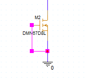
Step 28: Click to wire the ground and source. Click to place another wire between gate and ground. Press Escape on the keyboard when finished.
Step 29: Select PSpice > Run from the menu.
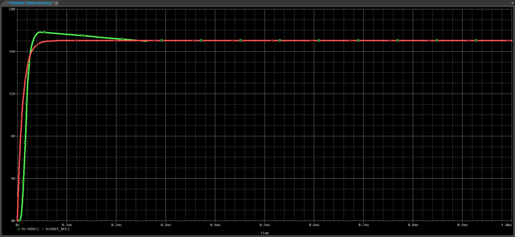
Step 30: View the results. The output voltage now holds steady around 17V.
Wrap Up & Next Steps
Quickly analyze realistic circuit behavior with access to extensive SPICE models, wizard-based model creation, and easy model import to create SPICE models in PSpice. Test out this feature and more with a free trial of OrCAD. Want to learn more about PSpice? Get access to free how-tos, courses, and walk-throughs at EMA Academy.
