Components in today’s high-speed and high-power designs must be placed carefully on the PCB to avoid any issues with signal integrity. For example, high-speed processors must be as close to their smoothing capacitors and other peripherals as possible. One method to achieve optimal component placement, is to create rooms for component placement to group components in certain areas on the board. With OrCAD PCB Designer, quickly create rooms for component placement to efficiently optimize your PCB layout.
This quick how-to will provide step-by-step instructions on how to create rooms for component placement using the Room property in OrCAD PCB Designer.
To follow along, download the provided materials above the table of contents.
How-To Video
 Open in New Window
Create Rooms for Component Placement
Note: Room names must match the names defined and associated with components in OrCAD Capture. Learn how to assign rooms in OrCAD Capture with our how-to.
Step 1: Open the provided design in OrCAD PCB Designer.
Step 2: In PCB Designer, select Shape > Rectangular from the menu.
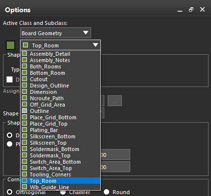
Step 3: In the Options panel, set the Active Class and Subclass to Board Geometry and Top_Room.
Step 4: Click to start drawing the rectangle on the left edge of the board, then click again to finish.
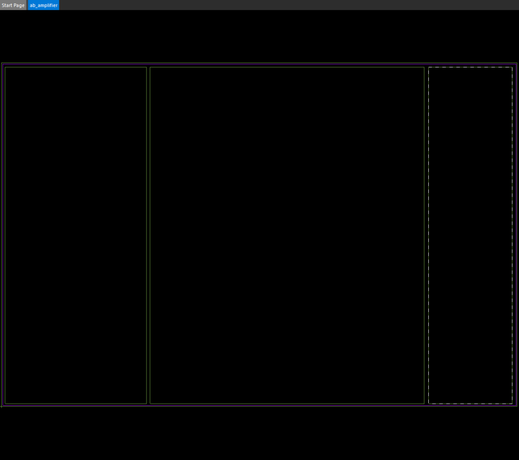
Step 5: Click to start drawing the rectangle in the middle of the board, then click again to finish.
Step 6: Click to start drawing the rectangle on the right edge of the board, then click again to finish. Right-click and select Done when finished.
Step 7: Select Add > Text from the menu.
Step 8: In the Options panel, set the Active Class and Subclass to Board Geometry and Top_Room. Set the Text Block to 6.
Step 9: Select the leftmost room rectangle to attach the text to that room.
Step 10: Click the location to place the text.
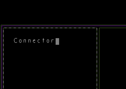
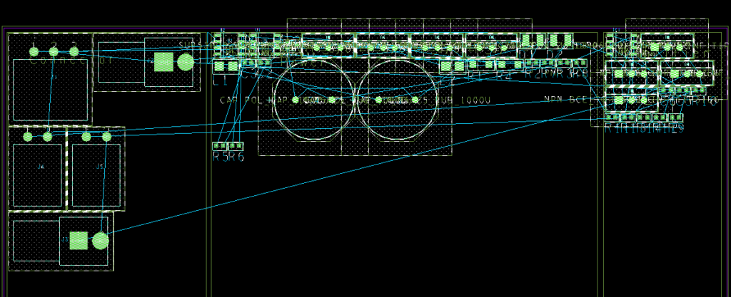
Step 11: Enter Connector for the name and press Enter.
Note: Only components in the Connector room will be allowed to be placed in this area.
Step 12: Select the middle room rectangle. Click the location to place the text.
Step 13: Enter Power for the name and press Enter.
Step 14: Select the right room rectangle. Click the location to place the text.
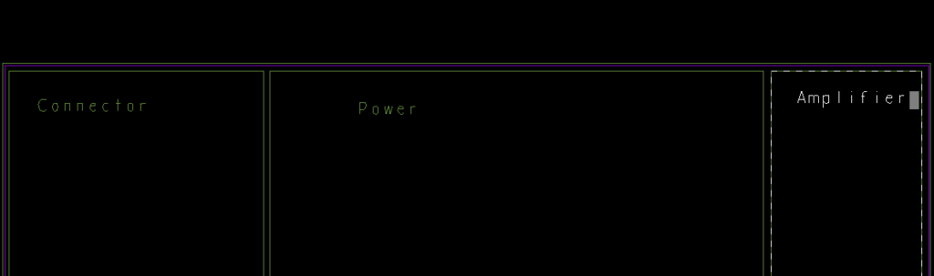
Step 15: Enter Amplifier for the name and press Enter. Right-click and select Done when finished.
Placing Components
Step 16: Select Place > Quickplace from the menu.
Step 17: Under Placement Filter, select Place By Room.
Note: All Rooms is selected by default.
Step 18: Click Place. The components are placed in their respective rooms and can be moved from there.
Step 19: Click OK.
Wrap Up & Next Steps
Quickly create rooms for component placement and group components in their optimal locations to keep distances short using OrCAD PCB Designer. Test out this feature and more with a free trialof OrCAD. Get more how-tos for OrCAD at EMA Academy.

