With electronic components and designs getting more compact every day, it is critical to ensure that boards meet all manufacturing requirements. A board with thinner traces and less spacing requires high precision, is more expensive and time-consuming to produce, and can be more prone to manufacturing defects; however, these requirements may be needed to meet the technological and functional demands associated with cutting-edge components like BGAs. Designers can create region-based rules for BGAs constraining the board to allow thinner or closer traces only where required, limiting the high precision to specific areas on the board. OrCAD X Presto includes the ability to quickly and easily create region-based rules for BGAs allowing designers to define constraint regions and assign different rule sets to sections of the board.
This quick how-to will provide step-by-step instructions on how to create region-based rules for BGAs in OrCAD X Presto.
To follow along, download the provided files above the table of contents.
How-To Video
 Open in New Window
Create a Constraint Set
Step 1: Open the provided design in OrCAD X Presto 24.1.
Step 2: Before a constraint set can be assigned to any region on the board, a constraint region rule set must be created. Select Tools > Constraint Manager from the menu.
Step 3: The Constraint Manager window opens. Select the Physical domain from the Worksheet Selector.
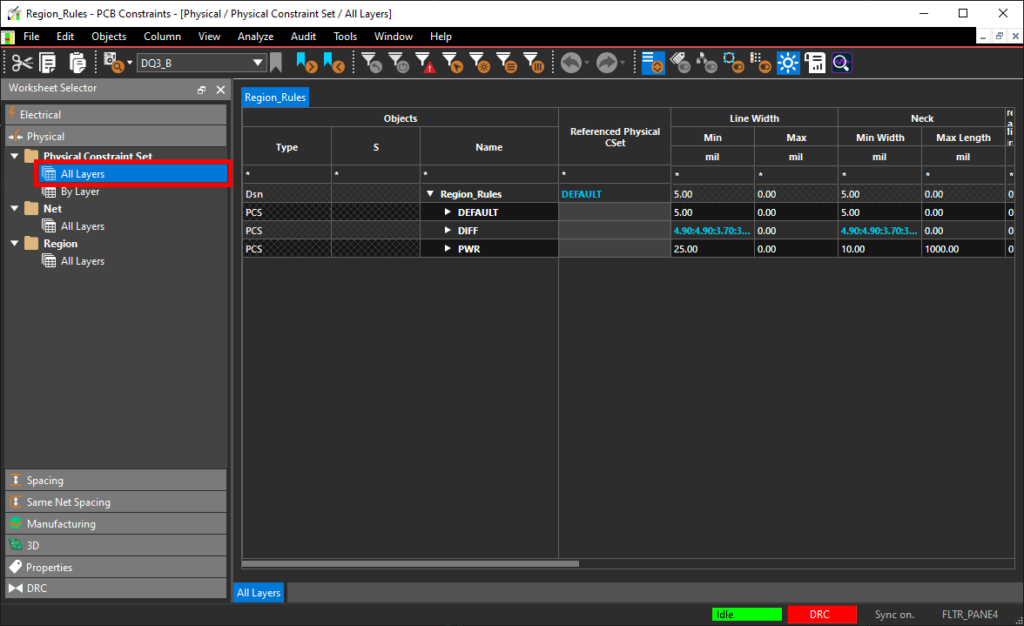
Step 4: Select the Physical Constraint Set > All Layers worksheet.
Step 5: Right-click the Default constraint set in the table and select Create > Physical CSet.
Step 6: The Create Physical CSet window opens. Enter the name BGA and click OK to create a new set.
Step 7: The BGA constraint set is added to a new row. Within the row, select the following cells and enter the following constraint values:
- Minimum Line Width: 3.7
- Minimum Neck Width: 3.7
- Maximum Neck Length: 200
Create Region-Based Rules for BGAs
Step 8: Select the Region > All Layers worksheet.

Step 9: Select the cell under Referenced Physical CSet for the BGA region and select BGA from the dropdown. The BGA constraint set is assigned to this region and its classes.
Step 10: Select the Spacing domain and the Region > All Layers worksheet.
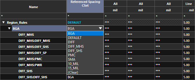
Step 11: In the BGA row, select the cell under Referenced CSet Spacing and select BGA. The BGA CSet is assigned to all classes and class-class pairs.
Close the Constraint Manager.
Note: In this board, a spacing constraint set for BGA components has already been defined. For more information on creating a constraint set, see the step-by-step how-to here.
Enabling Constraint Region Visibility
Step 12: Select Visibility on the left side of the canvas to open the Visibility panel.
Note: If the Visibility button is not present, select View > Panels > Visibility from the menu.
Step 13: Expand the Objects and Areas subpanel if it is not already open.
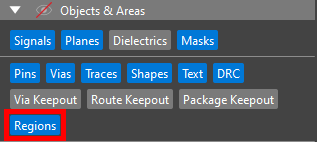
Step 14: Select Regions to enable visibility options for constraint regions. A new column of layer colors appears.
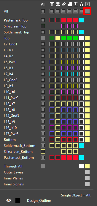
Step 15: Select the square under the Region column for All to turn on visibility for constraint regions in all layers.
Note: On the board, an outline is shown around the lower BGA component.
Step 16: Click Visibility again to close the Visibility panel.
Assigning a Constraint Region
Step 17: Select the outline around the lower BGA component to assign a region constraint set to it.
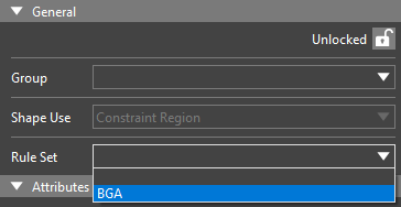
Step 18: The Properties panel populates with shape properties. Select BGA from the Rule Set dropdown.
Step 19: Click outside the shape to deselect.
Routing Between Regions

Step 20: To confirm that the physical constraints take effect inside the constraint region, select the Add Connect mode from the toolbar.
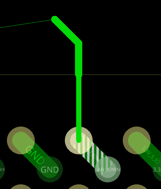
Step 21: Click one of the signal vias inside the BGA region to start routing a trace. Move your mouse to outside the region. The trace widens automatically.
Press Escape on the keyboard to cancel routing.
Defining a Constraint Region Area

Step 22: Select the Add Shape mode from the toolbar.
Step 23: The Add Shape widget opens. Select Constraint Region from the Shape Use drop-down menu and All from the Layer drop-down menu.
Step 24: Select BGA from the Rule Set dropdown.
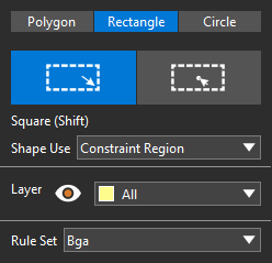
Step 25: Select Rectangle from the top of the widget to draw a rectangle.
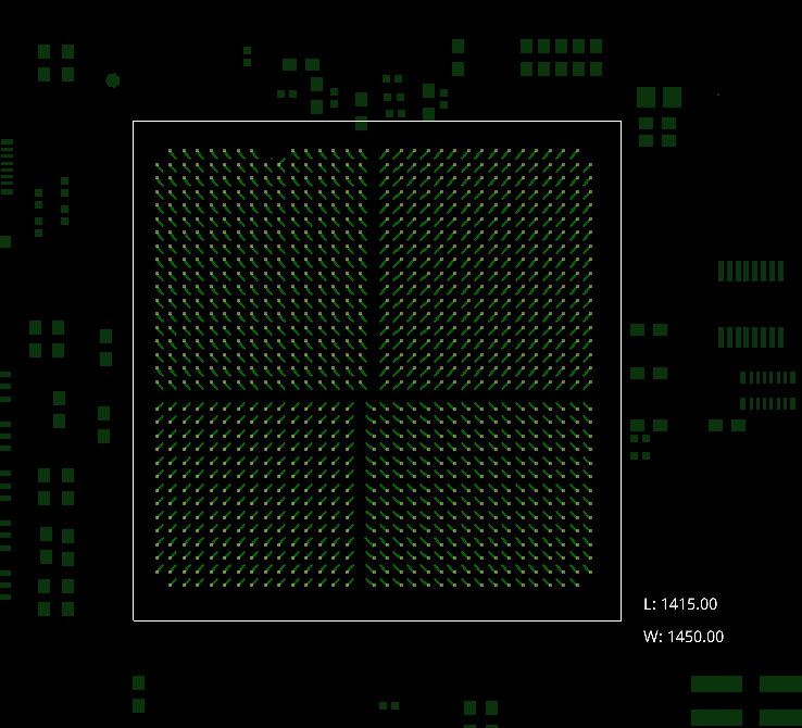
Step 26: Click to start drawing a rectangle in the top-left corner of the BGA area and click again to finish in the bottom-right. When finished, choose the Select mode from the toolbar. Click anywhere in the canvas to deselect the shape.
Confirming the Region
Step 27: Select the Add Connect mode from the toolbar.
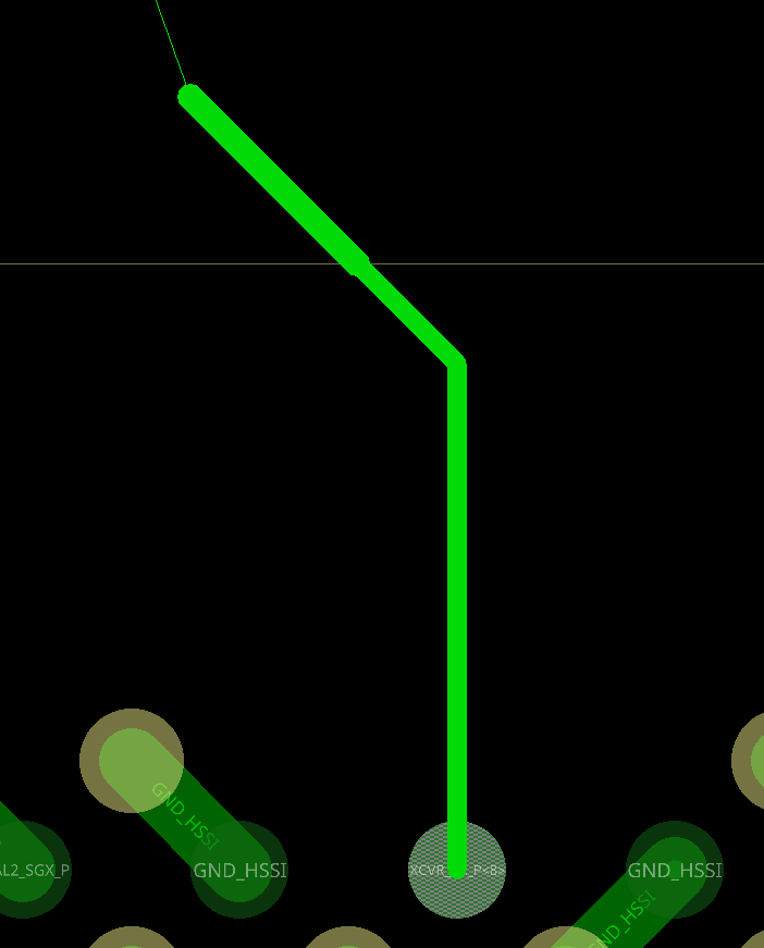
Step 28: Click to start routing a trace from the unconnected BGA pin. Outside the constraint region, the trace widens to the constraint width.
Press Escape to cancel routing and choose the Select mode from the toolbar.
Wrap Up & Next Steps
Quickly create region-based rules for BGAs to define specific trace width and spacing for different areas and technology on the PCB with OrCAD X Presto 24.1. To test this feature and more, get a free trial of OrCAD and start building. Want to learn more about OrCAD X Presto? Check out our other how-tos and step-by-step walkthroughs at EMA Academy.