Rigid-flex designs provide the versatility required to conform to the strict requirements of today’s PCB applications; however, rigid-flex designs pose additional challenges and complexities that must be addressed in the design process- including the ability to create multiple stackups for each section of the design. The stackup for rigid portions of the PCB are going to drastically different than the flex portions and must be communicated accurately to ensure manufacturability. OrCAD X Presto enables you to efficiently define multiple stackups for rigid-flex designs to support the varying layers and materials required for PCB fabrication.
This quick how-to will provide step-by-step instructions on how to create multiple stackups for rigid-flex PCB designs in OrCAD X Presto.
To follow along, download the provided files above the table of contents.
How-To Video
 Open in New Window
Activating the Cross Section Editor in OrCAD X Presto
Step 1: Open the provided design in OrCAD X Presto.
Step 2: Select Tools > Cross Section from the menu.
Step 3: View the stackup. Only a primary stackup is visible with top, bottom, soldermask, pastemask, and silkscreen layers.
Create Multiple Stackups
Step 4: Select View > Multi Stackups Mode.
Step 5: Select the + to add a new stackup configuration.
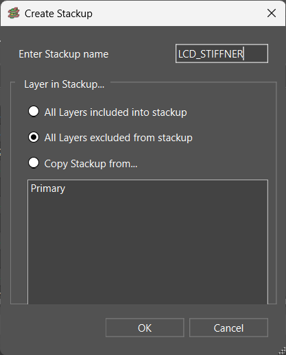
Step 6: Under Enter Stackup name, add LCD_STIFFENER. Here you have the ability to:
- Add all defined layers to the stackup
- Exclude all defined layers to the stackup
- Copy the stackup from an existing stackup
Leave the selection as exclude and click OK.
Step 7: View the Cross Section Editor. LCD_STIFFENER has been added as a tab across the top and in the main section of the Cross Section editor, allowing you to select the layers included in the stackup.
Importing IPC-2581
Note: An IPC-2581 file can be imported into the Cross Section editor to quickly define the layers and stackups required for your PCB designs. This can be obtained from previous known-good designs or manufacturers such as Sierra Circuits.
Step 8: Select Import > IPC2581.
Step 9: If you receive a warning that the operation cannot be undone. Click Yes to continue.
Step 10: Browse to the provided IPC-2581 file. Here you have the ability to:
- Merge with what is existing in the cross-section editor
- Replace what is existing in the cross-section editor
- Overwrite any existing stackup in the cross-section editor
Since we have defined a stackup in the cross-section editor, select Merge and click Open.
Step 11: When the import is finished a report is generated detailing the changes. Close the report and view the Cross Section editor. Additional stackups and layers have been added according to the IPC-2581 file.
Adding Layers to the Cross-Section
Step 12: To manually add layers to the stackup, right-click Coverlay Inner1 and select Add Layers.
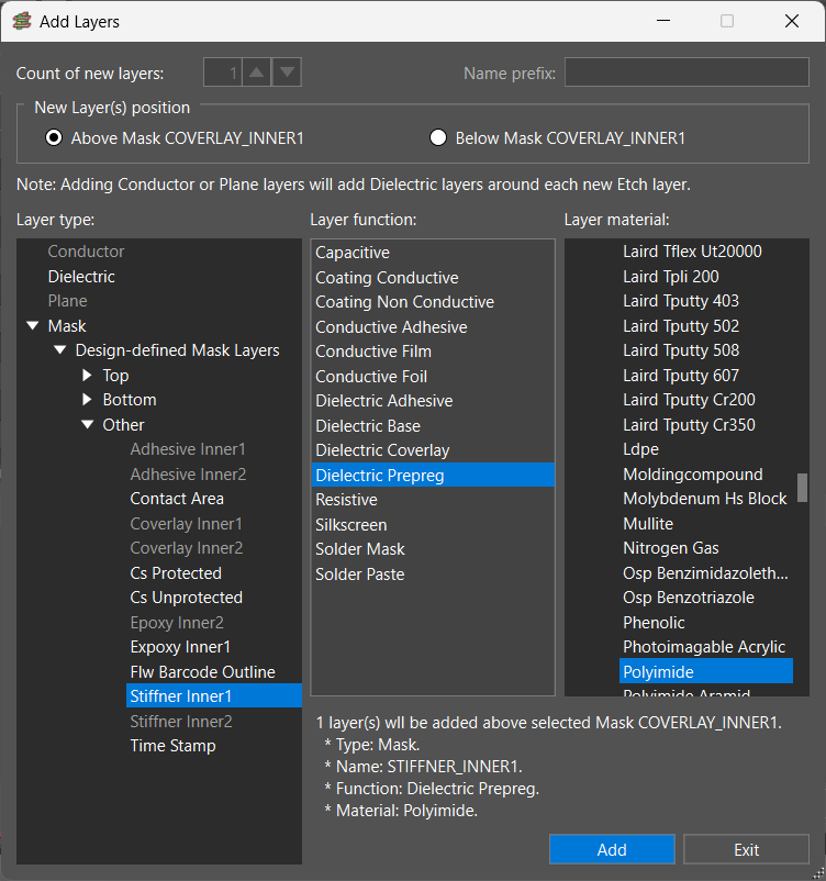
Step 13: Select to add the layer Above Mask Coverlay_Inner1.
Step 14: Expand Masks > Design Defined Mask Layers > Other and select Stiffner Inner1.
Step 15: Define the Layer Function as Dielectric Prepreg.
Step 16: Select the Layer Material as Polyimide and click Add.
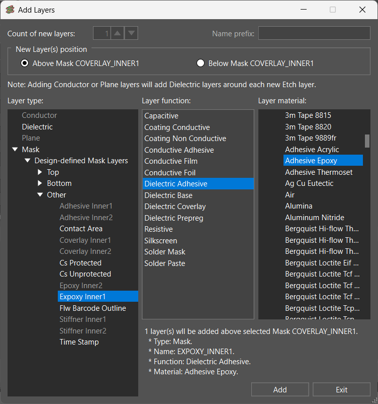
Step 17: Select Epoxy Inner1 from the Mask Layers.
Step 18: Define the Layer Function as Dielectric Adhesive.
Step 19: Select the Layer Material as Adhesive Epoxy and click Add.
Step 20: Select Exit. The new layers have been added to the stackup above Coverlay Inner1.
Defining Layers Included in Multiple Stackups

Step 21: Click the checkbox to exclude the Stiffner Inner1 and Epoxy Inner1 layers from the following stackups:
- Primary
- Flex1
- Flex1_Stiffener
Step 22: Under the LCD_Stiffener stackup, click the checkboxes to select the following layers:
- Inner1
- Polyimide between Inner1 and Inner2
- Inner2
- Adhesive_Inner2
- Coverlay_Inner2
Step 23: Select Apply.
Viewing Multiple Stackups
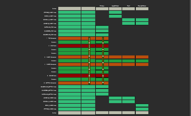
Step 24: View the visual graphic. Here you can see each stackup and the layers included.
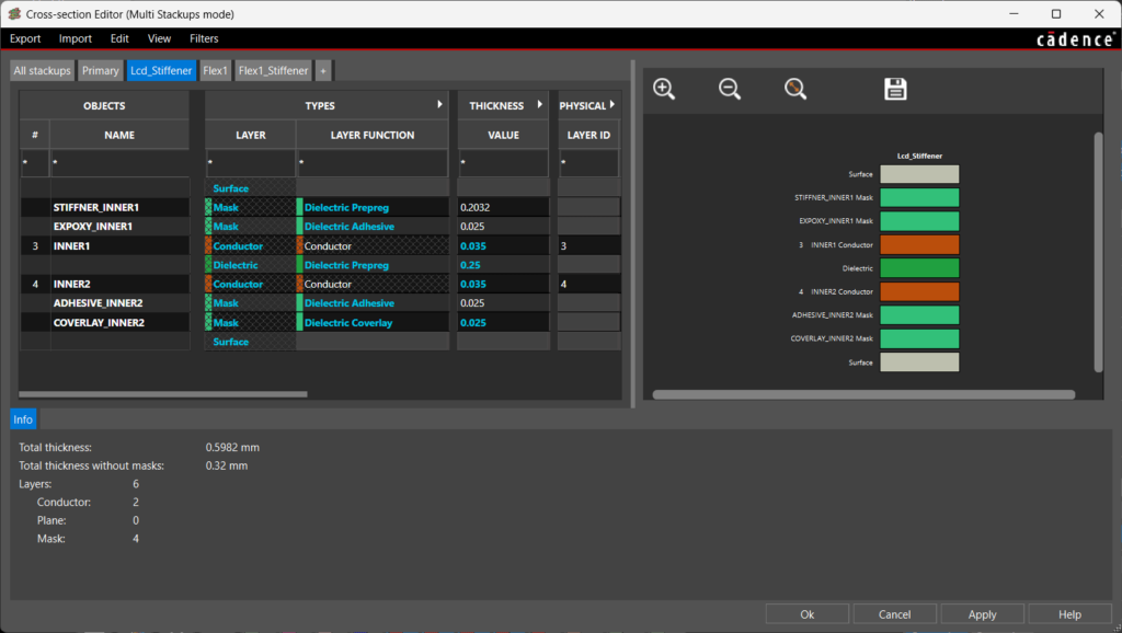
Step 25: Select a tab across the top, such as LCD_STIFFENER, to view the layers included in that specific stackup and detailed information including thickness, layer function, layer material, and more.
Note: If this is a commonly used cross section, select Export > IPC2581 to reuse the stackup configuration in future designs. To learn how to assign these stackups to specific zones on the PCB, view our how-to.
Step 26: Click OK to close the Cross Section Editor.
Wrap Up & Next Steps
Create multiple stackups for rigid-flex PCB designs to accurately communicate the vertical design intent and materials required for PCB manufacturing with OrCAD X Presto. Learn best practices for designing flex stackups with our on-demand webinar here.
Test out this feature and more with a free trial of OrCAD X. For more how-tos and step-by-step walk-throughs, visit EMA Academy.