Accurate manufacturing documentation is crucial to successful PCB fabrication and assembly; however, creating all the required drawings can be time-consuming and error-prone, especially when modifications are made to the PCB. OrCAD X Presto includes LiveDoc which allows users to quickly create accurate manufacturing documentation with pre-defined templated views, an easy-to-use interface, and automatic updates.
This how-to will provide step-by-step instructions on how to create manufacturing documentation in OrCAD X Presto with LiveDoc.
To follow along, download the provided files above the table of contents.
How-To Video
 Open in New Window
Create a Fabrication Drawing
Step 1: Select Manufacturing > LiveDoc > Create New from Template. LiveDoc opens as a new tab in OrCAD X Presto with a fabrication drawing pre-populated.
Step 2: Select the board view at the top of the fabrication drawing.
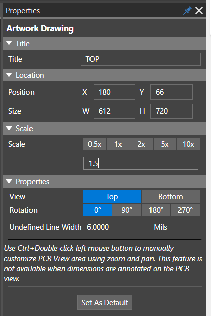
Step 3: In the Properties panel, under Scale enter 1.5 in the text field. Select anywhere in the canvas or press Tab on the keyboard to enter the value.
Note: In the Properties Panel, additional settings can be configured for the drawing including:
- Title
- Position
- Size
- Board View
- Rotation
- Undefined Line Width
Click and drag the board views to adjust on the LiveDoc canvas as needed.
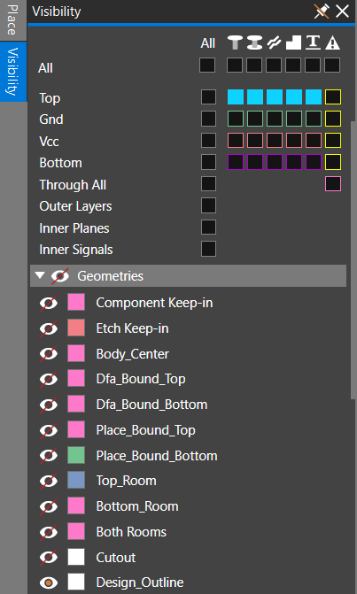
Step 4: Select the Visibility tab. Under Geometries, select the eye icon next to Design_Outline to display the board outline in the board view.
Step 5: Select the board view at the bottom of the fabrication drawing and set the Scale to 1.5 in the properties panel. Select anywhere in the canvas or press Tab on the keyboard to enter the value.
Step 6: Select the Visibility tab. Under Geometries, select the eye icon next to Design_Outline to display the board outline in the board view.
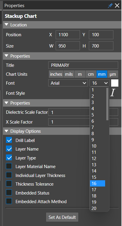
Step 7: Select the stack-up detail in the fabrication drawing. In the properties panel, select the arrow for the font size and choose 16.
Note: In the Properties Panel, additional settings can be configured for the drawing including:
- Title
- Position
- Size
- Units
- Scale Factors
- Information displayed in the stack-up chart
Step 8: Select the stack-up table from the fabrication drawing. In the properties panel, select the arrow for the font size and choose 16.
Note: In the Properties Panel, additional settings can be configured for the drawing including:
- Title
- Units
- Position
- Size
- Columns and information displayed in the stack-up table
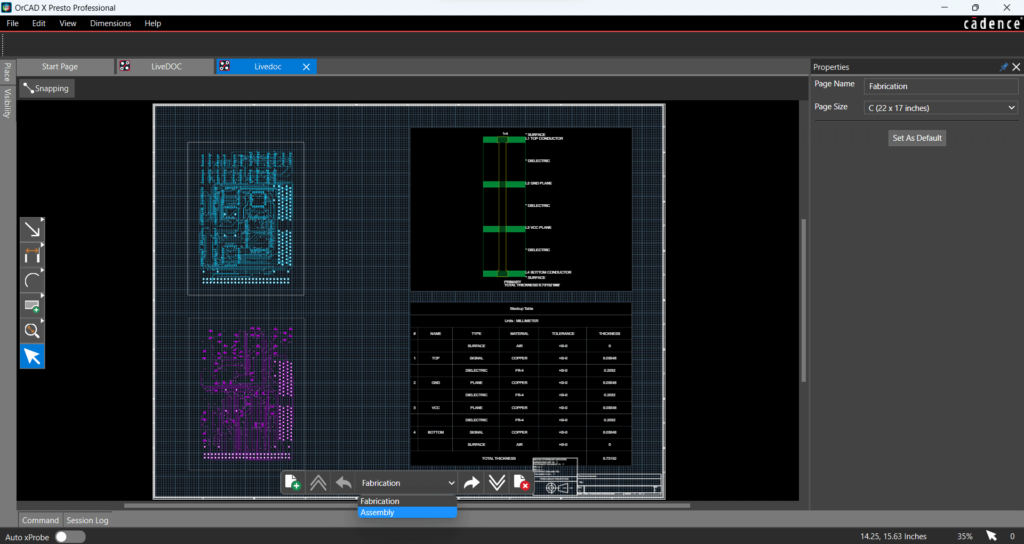
Step 9: At the bottom of the LiveDoc window, select the arrow next to Fabrication and choose Assembly from the drop-down menu.
Create an Assembly Drawing
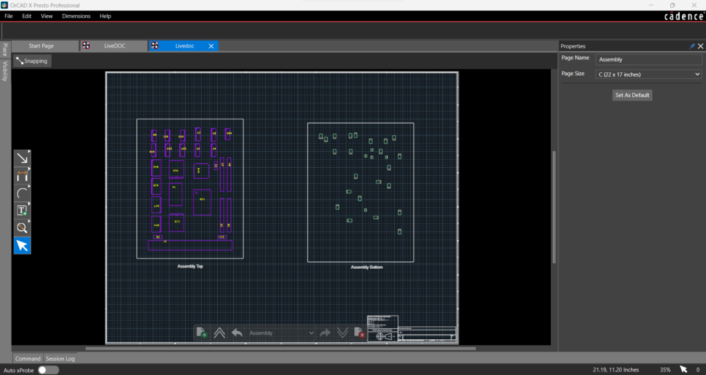
Step 10: Select the board view at the top of the assembly drawing and set the Scale to 2x in the properties panel.
Note: In the Properties Panel, additional settings can be configured for the drawing including:
- Title
- Position
- Size
- Board View
- Rotation
- Hole Display
- Minimum Diameter
Step 11: Select the board view at the bottom of the assembly drawing click and drag to adjust the view position.
Step 12: In the properties panel, set the Scale to 2x.
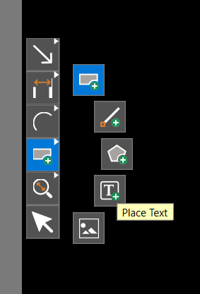
Step 13: Right-click the Place Rectangle icon on the toolbar and select the Place Text icon.
Step 14: Click the canvas below the Assembly Top View. Type Assembly Top and click anywhere in the canvas.
Step 15: With the text still selected, in the Properties Panel, select the arrow for the font size and choose 25.
Step 16: With the text still selected, use CTRL+C to copy the text and CTRL+V to paste. Click the canvas under the Assembly Bottom view.
Step 17: Double-click the text to edit and adjust the text to read Assembly Bottom. Select anywhere in the canvas when done.
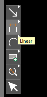
Step 18: From the toolbar, select the Linear Dimension icon.
Step 19: Click to select a point on the board and click to select another point.
Step 20: Move the cursor to adjust the location of the dimension on the canvas, then click to place.
Step 21: Select the Arrow icon from the toolbar or use Escape on the keyboard then select the newly placed dimension.
Step 22: In the Properties Panel, select the arrow for the font size and choose 25.
Step 23: Select Set as Default.
Note: This will retain your settings for the dimension and automatically apply them to any future dimensions placed within the LiveDoc canvas.
Step 24: Select the Linear Dimension icon from the toolbar.
Step 25: Click to select a point on the board and click to select another point.
Step 26: Move the cursor to adjust the location of the dimension on the canvas, then click to place. The newly placed dimension has been adjusted to reflect the new default settings.
Create Manufacturing Documentation
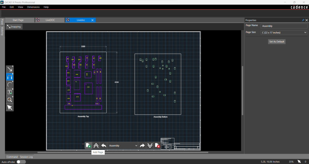
Step 27: Select the Add Page button from the bottom toolbar in the LiveDoc canvas.
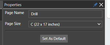
Step 28: In the Properties Panel, change the Page Name to Drill.
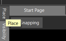
Step 29: Select the Place tab on the left of the LiveDoc canvas. Here you can select from pre-defined views and objects to quickly create the required manufacturing documentation.
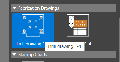
Step 30: Scroll down to the Fabrication Drawing section and select Drill Drawing 1-4.
Step 31: Click to place the drawing in the LiveDoc canvas.
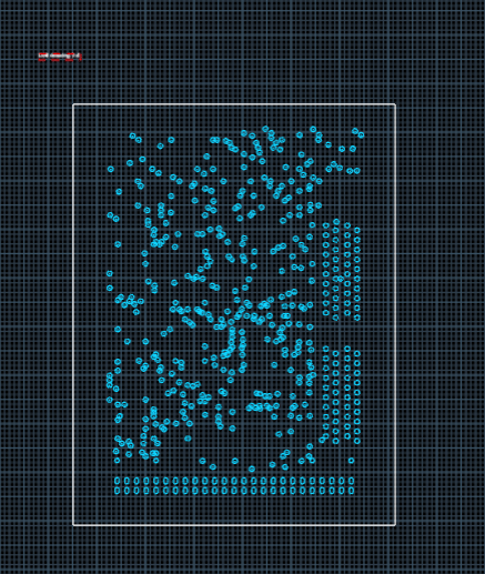
Step 32: With the board view selected, in the properties panel set the Scale to 2x.
Step 33: Select the accompanying text. In the Properties Panel, select the arrow for the font size and choose 25 from the drop-down menu.
Note: Click and drag the text to adjust the drill drawing as needed.
Step 34: Select the Place tab and choose Drill Chart 1-4 from the template views.
Step 35: Click and drag the mouse to the desired size for the drill chart then release the mouse.
Step 36: Click to select the drill chart. In the properties panel, select the arrow for the font size and choose 16.
Note: In the Properties Panel, additional settings can be configured for the drill chart including:
- Title
- Position
- Size
- Units
- Sorting
- Columns and information displayed in the chart
Step 37: Repeat this process as needed to create the required manufacturing documentation.
Automatic Documentation Updates
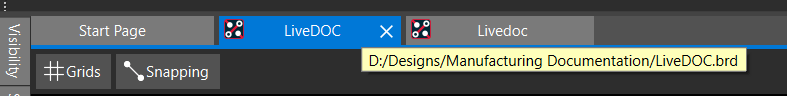
Step 38: Select the LiveDOC.brd tab to view the PCB design.
Step 39: Select Tools > Mechanical from the menu.
Step 40: Select MTG250 from the list of available mechanical symbols.
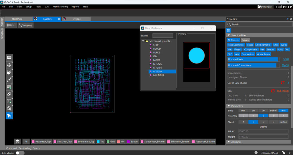
Step 41: Click to place a mounting hole in each corner of the PCB.
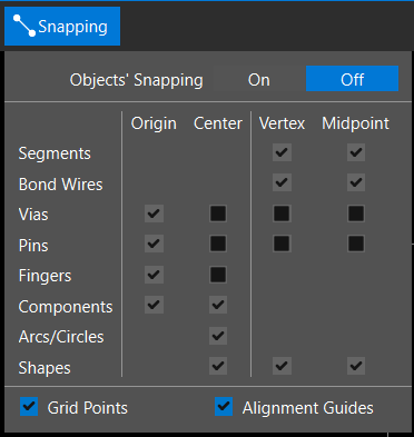
Note: If mounting holes are snapping to locations on the PCB which make them difficult to place, select the snapping tab in the PCB canvas and set Off.
Step 42: Select the X in the mechanical placement window to close.
Step 43: Select the Livedoc documentation tab.
Step 44: View the Drill drawing. The mounting holes have been automatically added and the drilling drawing and chart have been updated accordingly.
Wrap Up & Next Steps
Quickly create manufacturing documentation for your PCBs using templated views and automatic updates with LiveDoc in OrCAD X Presto. Test out this feature and more with a free trial of OrCAD X Presto. For more how-to’s and step-by-step walk-throughs visit EMA Academy.
