Fanning out power and ground pins is a fundamental step in every PCB design process. Incorrect fanouts can have a detrimental effect on power integrity and fanouts which are not optimized can affect routing and layout success. Quickly create fanouts in OrCAD X Presto with easy-to-understand visual graphics that explain functionality and allow you to test fanout strategies to efficiently create your PCB layouts.
This quick how-to will provide step-by-step instructions on how to create fanouts in OrCAD X Presto Professional.
How-To Video
 Open in New Window
Activate Fanout Settings
Step 1: Open the desired design in OrCAD X Presto.
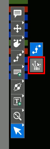
Step 2: Right-click the Add Connect mode in the toolbar and select Fanout. The Fanout mode is activated and the Fanout widget appears.
Note: There are three main modes for creating fanouts:
- Radial
- Linear
- Via in PAD
Radial is selected by default. These modes will be discussed in detail.
Create Fanouts in OrCAD X Presto for BGAs
Note: BGA fanouts can be completed with the radial fanout configuration.
Step 3: In the Fanout widget, click an arrow to set the direction of via placement.
Step 4: Select the center in the direction map. This will create a radial fanout.
Step 5: Select Constraint from the Trace Width dropdown.
Note: Constraints need to be configured to use this feature. See how to configure constraints here.
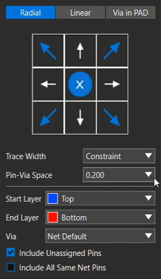
Step 6: Select 0.200 from the Pin-Via Space dropdown.
Note: You can also manually override the trace width. To center the vias between groups of BGA pins, select Centered from the Pin-Via Space dropdown.
Step 7: Set the Start Layer to Top and the End Layer to Bottom.
Step 8: Set the Via to Net Default.
Note: If your design has multiple available vias, they are listed in this dropdown menu. Vias can be configured in the Constraint Manager.
Other options are available for radial fanouts:
- Include Unassigned Pins: Check to fan out no-connect pins.
- Include All Same Net Pins: Check to fan out all pins on the same net, even if multiple vias are created.
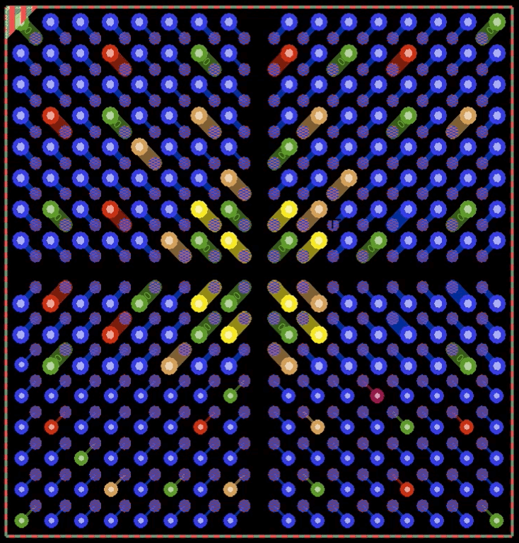
Step 9: Click to select a BGA chip on the canvas to create the fanout. The fanout vias are drawn in the appropriate directions.
Step 10: In the Fanout widget, select Via in Pad to create vias in the pads. This mode has the following options:
- Start and End Layer
- Via
- Include Unassigned Pins
- Include All Same Net Pins
Step 11: Select the BGA chip again. The BGA traces and vias are replaced with vias in each pad. The existing fanout traces and vias are deleted automatically.
Note: Fanouts can also be created for individual pins by turning off Components in the Selection Filter subpanel.
Configure Linear Fanouts
Step 12: Select Linear in the Fanout widget. A visual graphic displays additional information about the fanout including an explanation of the modifiable options.
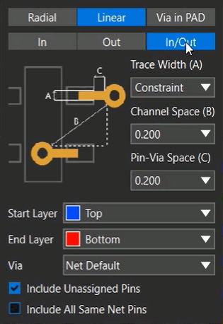
Step 13: Select In/Out below Linear. The preview image changes to an in/out linear fanout.
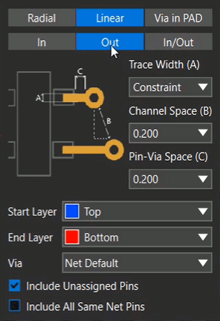
Step 14: Select Out. The preview image changes to an outward fanout.
Note: For linear fanouts the following options can be configured:
- Trace Width: The width of the trace. Can be the constraint width or manually overridden.
- Channel Space: The vector distance between two adjacent vias. If the component pins are close together, the vias must be drawn at different spacings.
- Pin-Via Space: The distance between pins and vias.
Step 15: In the Fanout widget, configure the following options:
- Trace Width: Constraint
- Channel Space: 0.200
- Pin-Via Spacing: 0.200
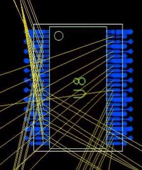
Step 16: Select a SOIC or TSSOP chip on your design to create the linear fanout.
Step 17: Press Escape on the keyboard to return to the selection mode.
Create Fanouts in OrCAD X Presto for Multiple Components
Note: Fanouts can be easily applied to components with the same packages.
Step 18: Click to select the component that a fanout was created for.
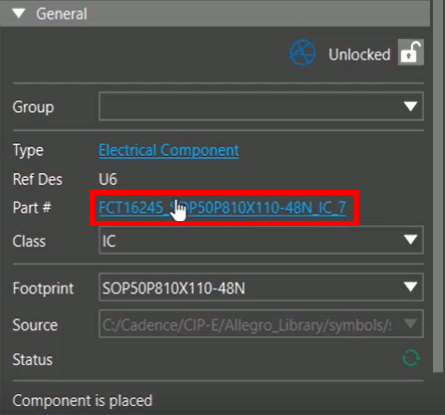
Step 19: In the Properties panel, select the hyperlink for the part number.
Step 20: With the Search panel selected, press CTRL-A on the keyboard to highlight the parts in the Search panel.
Step 21: Right-click one of the highlighted parts and select Select on Canvas. All parts are selected on the canvas.
Step 22: Select Fanout from the toolbar.
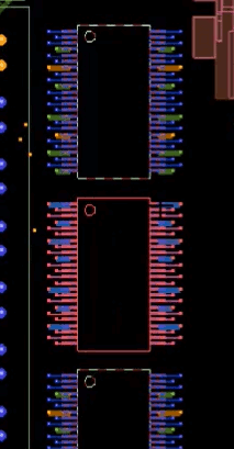
Step 23: Select one of the components on the canvas to create the fanout. The fanout is applied to all selected components.
Move Fanouts
Note: Once a fanout is applied, it is associated with the component and will move with it throughout the design.
Step 24: Select the Move mode from the toolbar to adjust a component.
Step 25: Click one of the fanned-out components. Both the fanout and component are attached to the cursor and can be moved.
Wrap Up & Next Steps
Quickly create fanouts in OrCAD X Presto to test fanout strategies and efficiently complete your PCB layouts. Test out this feature and more with a free trial of OrCAD X Presto. For more how-tos and step-by-step walk-throughs, visit EMA Academy.