Flex designs are increasing in popularity in applications which require versatility and space optimization in order to adhere to stricter requirements. To verify flex and rigid-flex designs, bendable areas must be accurately defined. OrCAD X allows you to efficiently create bends for flex designs, modify bends, and visualize the bendable areas in 3D.
This quick how-to will provide step-by-step instructions on how to create bends for flex designs using OrCAD X Presto.
To follow along, download the provided files above the table of contents.
How-To Video
 Open in New Window
Activating Bend Creation in OrCAD X
Step 1: Open the provided board file in OrCAD X Presto Professional. This design has some bends already defined.
Step 2: Select Setup > Flex > Create Bends from the menu.
Step 3: A tooltip appears directing you on the next steps to take. Navigate to the flex section of the design located under the rigid PCB which does not have bends defined.
Note: To configure tooltip preferences, select Edit > Preferences > Quick Help.
Create Bends for Flex Designs
Step 4: Click to start a bend line then click to finish the bend line.
Step 5: View the Properties Panel. Here information can be reviewed and configured for the bend.
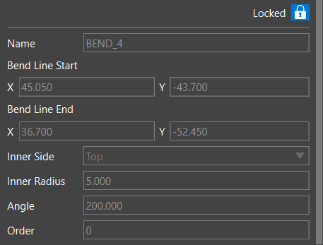
Step 6: Enter a Name for the bend. In this scenario, leave BEND_4.
Step 7: Set the Inner Side to Top. This is the side of the PCB you want to create the bend area.
Step 8: Set the Inner Radius to 5.
Step 9: Set the Angle to 200.
Step 10: Select the Lock icon to lock the bend to prevent unwanted modifications during the design process.
Note: To create a package keepout and via keepout larger than the bend area, set the oversize values.
Step 11: Click to start a new bend line in the other corner of the flex shape then click again to finish the bend line.
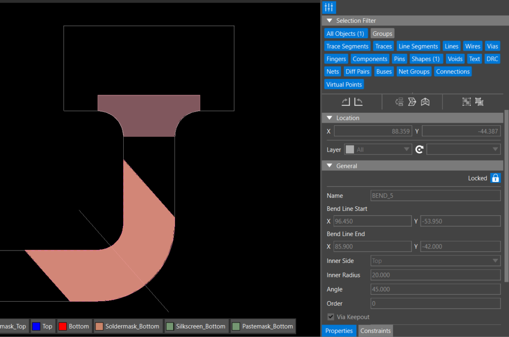
Step 12: Configure the following information for the bend:
- Name: Bend_5
- Inner Side: Top
- Inner Radius: 20
- Angle: 45
Step 13: Select the Lock icon to lock the bend to prevent unwanted modifications during the design process.
Step 14: Click to create a final bend in the straight portion of the flex element near the rigid board then click to finish the bend.
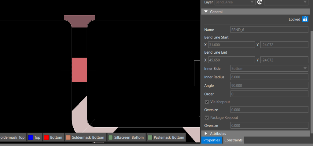
Step 15: Set the Y Coordinate for Bend Line Start to -24.072.
Step 16: Set the Y Coordinate for the Bend Line End to -24.072.
Step 17: Configure the following information for the bend:
- Name: Bend_6
- Inner Side: Bottom
- Inner Radius: 6
- Angle: 90
Step 18: Select the Lock icon to lock the bend to prevent unwanted modifications during the design process.
Viewing a Bend in 3D
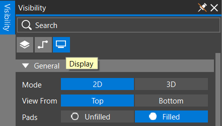
Step 19: Select the Visibility tab and Display.
Step 20: Under Mode, choose 3D. View the PCB in 3D. The bends are automatically shown in the bent state.
Step 21: In the Visibility tab, scroll down to the Bends section.
Step 22: Move the slider for All, all the way to the left to view the PCB before bending.
Step 23: Move any of the sliders to view how the bends will act in the PCB assembly or move the slider for All to bend all the sections at once.
Modifying a Bend
Step 24: Right click in the 3D canvas and select 2D/ 3D Toggle to transition to the 2D view or select 3 on the keyboard.
Step 25: Select Bend_6.
Step 26: In the Properties Panel, select the lock icon to unlock the bend.
Step 27: Change the angle to 180 and lock the bend.
Step 28: Right-click the PCB canvas and select 2D/ 3D Toggle (3) to return to the 3D view.
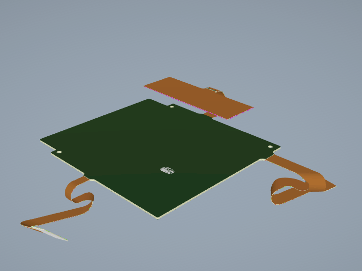
Step 29: View how the modification of the bend effected the PCB.
Wrap Up & Next Steps
Efficiently create bends for flex designs and visualize bends in 3D with OrCAD X Presto to verify your rigid-flex designs before production. Learn best practices for designing flex PCBs with our on-demand webinar here.
Test out this feature and more with a free trial of OrCAD X. For more how-tos and step-by-step walkthroughs, visit EMA Academy.