Voltage-controlled oscillators are an important tool when testing circuits such as FM demodulators, filters, and audio processors and equalizers; however, accurately creating the corresponding SPICE model can be time-consuming. With PSpice you can quickly create the required Voltage-Controlled Oscillator (VCO) SPICE model to create a realistic simulation by easily defining the type and signal value.
This quick how-to will provide step-by-step instructions on how to create a voltage-controlled oscillator SPICE model in OrCAD PSpice.
To follow along, download the provided files above the table of contents.
How-to Video

Creating a Voltage-Controlled Oscillator SPICE Model
Step 1: Open the provided design in OrCAD PSpice Designer.
Step 2: Select Place > PSpice Part > Modeling Application from the menu.
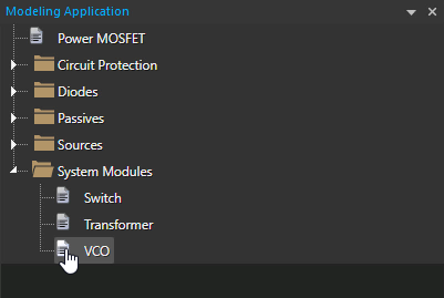
Step 3: In the Modeling Application, expand System Modules and select VCO.
Step 4: The PSpice Modeling Application VCO window opens. Select the VCO – Sinusoidal radio option to generate a sinusoidal VCO.
Note: A triangular or square wave VCO can be created as well.
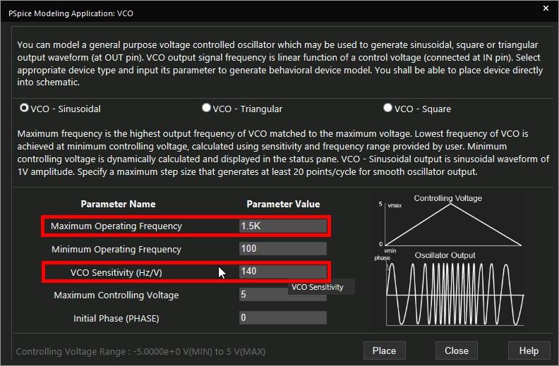
Step 5: Set the Maximum Operating Frequency to 1.5k and the VCO Sensitivity to 140.
Learn how to decipher a VCO datasheet to determine the parameters required for SPICE Model creation here.
Note: Additional options can be set for minimum operating frequency, maximum controlling voltage, and initial phase.
Step 6: Click Place to attach the source to your cursor.
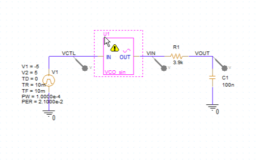
Step 7: Click to place the source in the schematic.
Running the Simulation
Step 8: Select PSpice > Run from the menu.
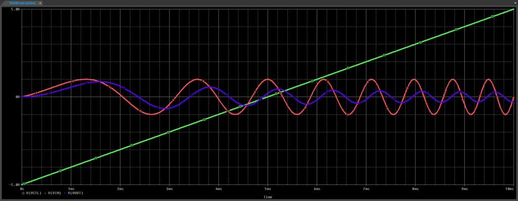
Step 9: View the simulation results. As the control voltage V(VCTL) increases, the input and output frequencies increase.
Modifying the Voltage-Controlled Oscillator SPICE Model
Step 10: Back in the schematic, select the VCO and press Delete on the keyboard.
Step 11: Select System Modules > VCO in the Modeling Application.
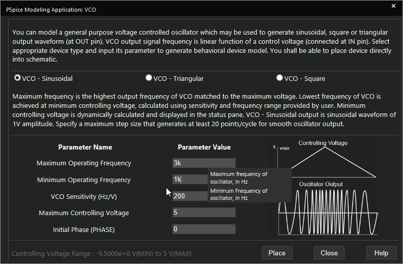
Step 12: Set the Maximum Operating Frequency to 3k and the Minimum Operating Frequency to 1k.
Step 13: Click Place to attach the source to your cursor.
Step 14: Click to place the source in the empty space.
Step 15: Select PSpice > Run from the menu.
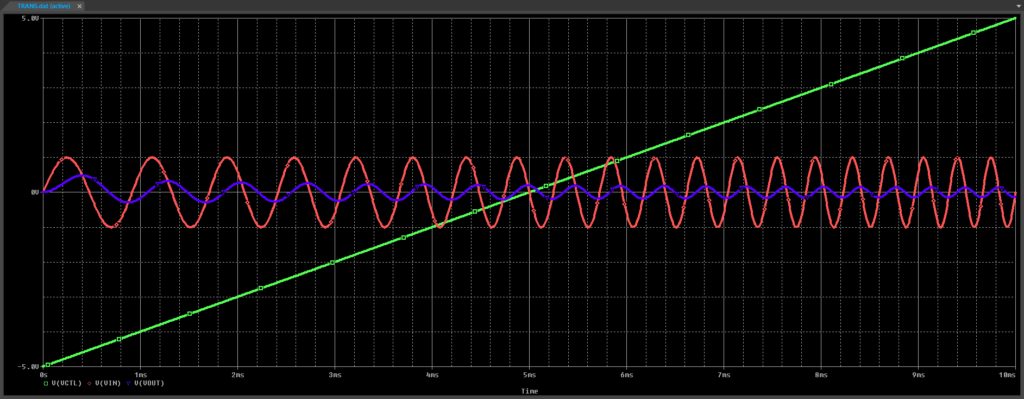
Step 16: View the simulation results. The VCO output frequencies are higher, and the output cuts off at higher frequencies.
Wrap Up & Next Steps
Quickly create the required Voltage-Controlled Oscillator SPICE model and simulate accurate circuit behavior with the modeling application in OrCAD PSpice. Test out this feature and more with a free trial of OrCAD.
To learn more about deciphering a VCO datasheet to determine the parameters required for SPICE Model creation, view our blog here.
