Implementing protection in a high-voltage circuit is critical to shield against voltage spikes. Typically, high-voltage protection is achieved by incorporating a Transient Voltage Suppressor (TVS) into the design. Simulating circuit behavior, including the TVS, is important to ensure adequate protection and prevent circuit failure. PSpice allows you to quickly define and create the required Transient Voltage Suppressor SPICE model to produce a realistic simulation.
This quick how-to will provide step-by-step instructions on how to create a transient voltage suppressor SPICE model in OrCAD PSpice.
To follow along, download the provided files above the table of contents.
How-To Video

Running the Unprotected Simulation
Step 1: Open the provided design in OrCAD PSpice Designer.
Step 2: Select PSpice > Run from the menu.
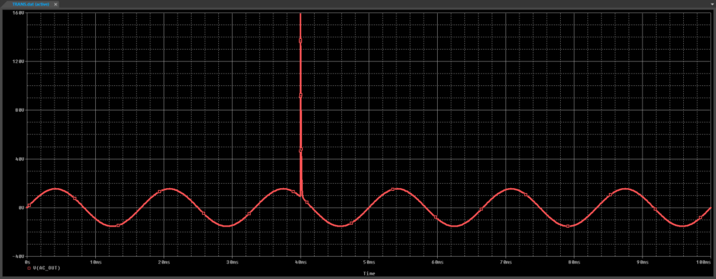
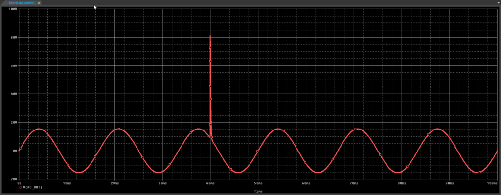
Step 3: View the simulation results. A sine wave with a strong voltage spike is shown. Close the result window.
Creating a Transient Voltage Suppressor SPICE Model
Step 4: Select Place > PSpice Part > Resistor from the menu.
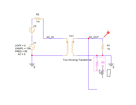
Step 5: Click to place the resistor in the circuit. Right-click and select End Mode.
Note: Use R on the keyboard to rotate the component.
Step 6: Double-click the resistor value 1k to change it.
Step 7: Enter 1m for a new value of 1 milliohm and click OK.
Step 8: Select Place > PSpice Part > Modeling Application from the menu.
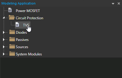
Step 9: In the Modeling Application, expand Circuit Protection and select TVS.
Step 10: The Transient Voltage Suppressors window opens. Select the option to create Transient Voltage Suppressors with Lead Inductance.
Step 11: Enter the following parameter values:
- Voltage at I1 (V1): 48
- Current at V2 (I2): 5.2
- Voltage at I2 (V2): 53.3
- Capacitance: 20p
- Lead Inductance: 15n
- Temperature Coefficient %: 0.1
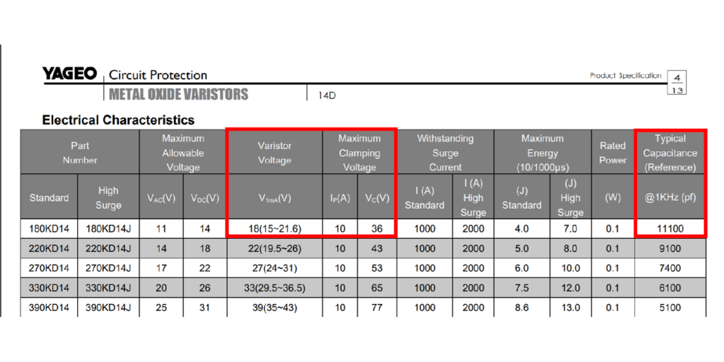
Note: These values can be obtained from the suppressor’s datasheet. Additional options are available for on-state resistance and tolerance.
Learn how to decipher a TVS datasheet to determine the parameters required for SPICE Model creation here.
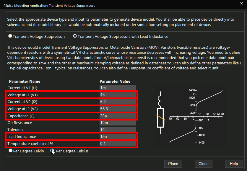
Step 12: Select Per Degree Celsius for the temperature coefficient.
Step 13: Click Place to attach the component to your cursor.
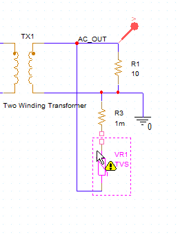
Step 14: Click to place the TVS in the circuit.
Note: Place the TVS such that one terminal touches the unconnected terminal of the resistor.
Step 15: Select Place > Wire from the menu or W on the keyboard. Complete the connection between the TVS and resistor.
Running the Protected Simulation
Step 16: Select PSpice > Run from the menu.
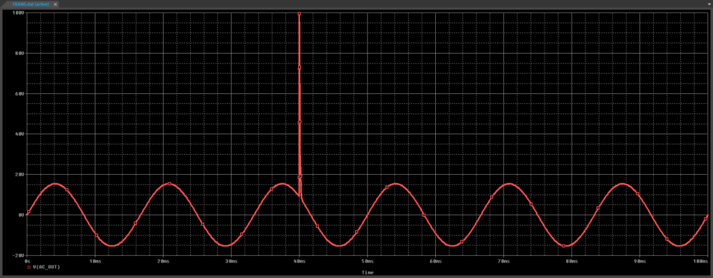
Step 17: View the simulation results. The spike amplitude is reduced to 100Vpk.
Modifying the Transient Voltage Suppressor SPICE Model
Step 18: Back in the schematic, right-click the TVS and select More > Edit PSpice Component.
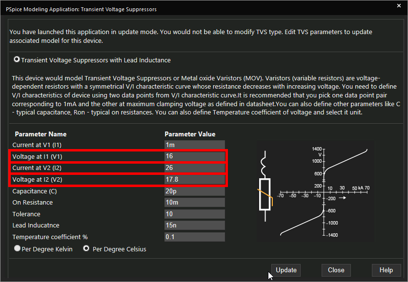
Step 19: Change the following parameters:
- Voltage at I1: 16
- Voltage at I2: 17.8
- Current at V2: 26
Step 20: Click Update.
Step 21: Select PSpice > Run from the menu.
Step 22: View the results. The spike amplitude is now reduced to 80V.
Wrap Up & Next Steps
Quickly create the required SPICE Models for transient voltage suppressors to accurately simulate circuit behavior and ensure adequate circuit protection with the modeling application in OrCAD PSpice. Test out this feature and more with a free trial of OrCAD. To learn more about how to determine the parameters required for a TVS SPICE model from the device datasheet, view our blog here.

