Every SPICE simulation needs to have an accurate source or input signal for a realistic analysis. For testing heavy-duty power systems or loads such as AC motors, the ability to quickly simulate a three-phase source is key. PSpice allows you to quickly create the required three-phase source SPICE model, in Delta or Star (Y) configuration, for a realistic simulation.
This quick how-to will provide step-by-step instructions on how to create a three-phase source SPICE model in OrCAD PSpice.
To follow along, download the provided files above the table of contents.
How-To Video

Creating a Three-Phase Source SPICE Model
Step 1: Open the provided design in OrCAD PSpice Designer.
Step 2: Select Place > PSpice Part > Modeling Application from the menu.
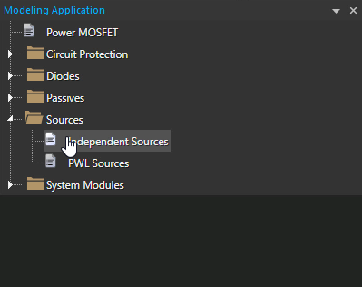
Step 3: In the Modeling application, expand Sources and select Independent Sources.
Step 4: Select the Three Phase tab.
Step 5: Select Star as the configuration.
Note: With a Delta three-phase source, the line voltage is equal to the phase voltage. With a Star (or Y) three-phase source, the line voltage is equal to the phase voltages times √3.
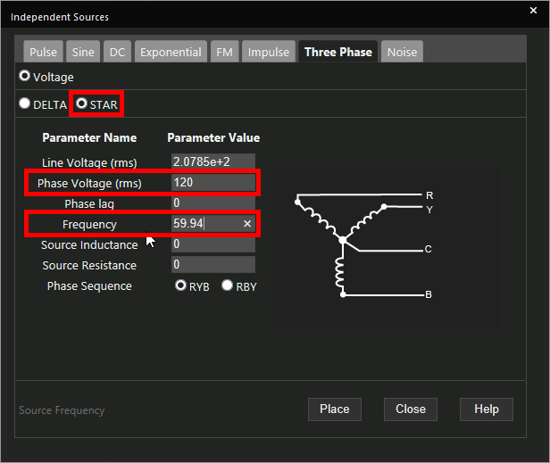
Step 6: Enter 59.94 for the Frequency and 120 for the Phase Voltage.
Note: Additional options are available to configure:
- line voltage
- phase voltages
- phase lag
- source inductance
- source resistance
- phase sequence
The phase and line voltages are adjusted accordingly depending on source type.
Learn how to determine the required parameters for a three-phase source SPICE Model here.
Step 7: Click Place to attach the source to your cursor.
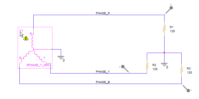
Step 8: Click to place the source in the schematic.
Running the Simulation
Step 9: Select PSpice > Run from the menu.
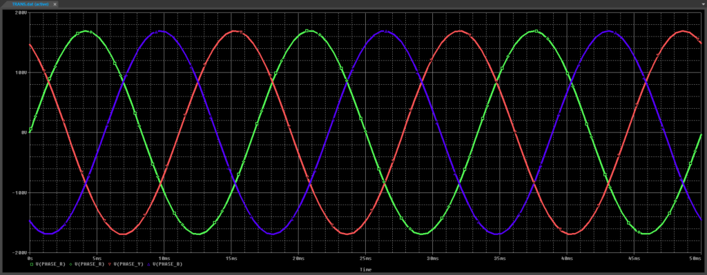
Step 10: View the simulation results. The three sine waves are plotted with the expected phase difference of 120°.
Modifying a Three-Phase Source SPICE Model
Step 11: Back in the schematic, select the three-phase source and press Delete on the keyboard.
Step 12: Select Independent Sources from the Modeling Application.
Step 13: Select the Three Phase tab.
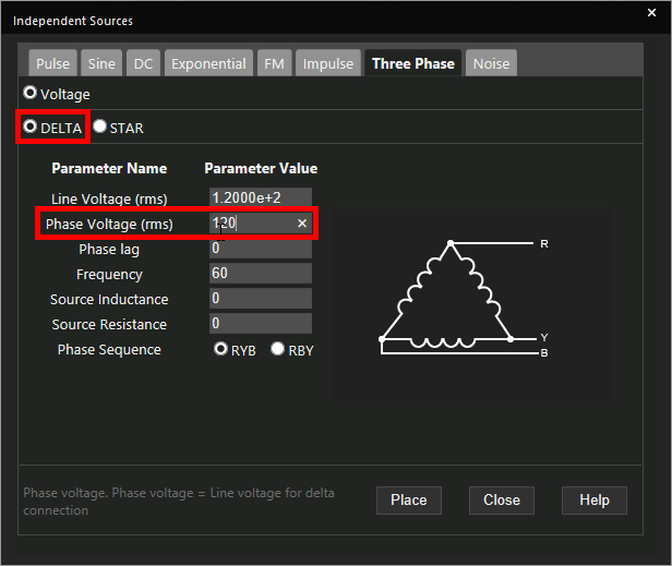
Step 14: Select Delta as the phase type and enter a Phase Voltage of 120.
Step 15: Click Place.
Step 16: Click to place the delta source in the schematic.
Step 17: Click and drag to select the unconnected ground and its wires. Press Delete on the keyboard.
Step 18: Select Place > Wire from the menu, the Wire button from the toolbar, or press W on the keyboard.
Step 19: Click to connect the delta source to the unconnected wires. Press Escape when finished.
Step 20: Select PSpice > Run from the menu.
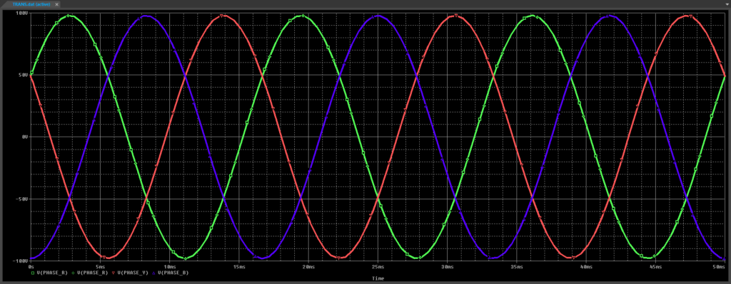
Step 21: View the results. A similar three-phase plot is shown.
Wrap Up and Next Steps
Quickly create the required three-phase source SPICE Model to accurately analyze circuit behavior with the modeling application in OrCAD PSpice. Test out this feature and more with a free trial of OrCAD. To learn how to determine the required parameters for a three-phase source SPICE Model in your circuit design, view our blog here.
