Most, if not all modern consumer electronics depend on input from the user to function as desired. Typically, this comes in the form of mechanical switches such as buttons on the device control panel or remote. To accurately analyze circuit behavior, these switches must be incorporated into the simulation. PSpice allows you to quickly create the required switch SPICE model to model realistic circuit behavior.
This quick how-to will provide step-by-step instructions on how to create a switch SPICE model in OrCAD PSpice.
To follow along, download the provided files above the table of contents.
How-To Video

Creating a Switch Model
Step 1: Open the provided design in OrCAD PSpice Designer.
Step 2: Select Place > PSpice Part > Modeling Application from the menu.
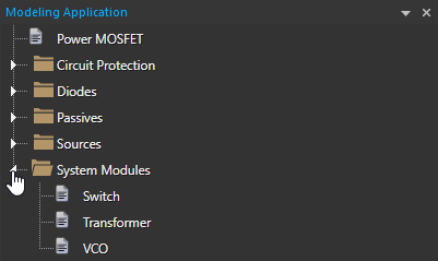
Step 3: In the Modeling Application, expand System Modules and select Switch.
Step 4: Select the Voltage Controlled tab to create a voltage-controlled switch.
Note: A time or current-controlled switch can also be created.
Step 5: Select S_ST to create a switch with hysteresis.
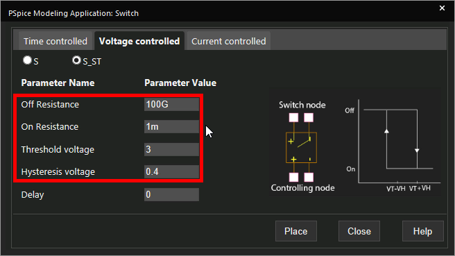
Step 6: Set the Threshold Voltage to 3 and the Hysteresis Voltage to 0.4.
Note: The switch will turn on when the controlling node voltage exceeds the Threshold Voltage plus Hysteresis Voltage. The switch will turn off when the controlling node voltage reduces to the Threshold Voltage minus the Hysteresis Voltage.
Step 7: Set the Off Resistance to 100G and the On Resistance to 1m.
Learn how to determine the required parameters for a switch SPICE Model here.
Note: The switch delay can also be configured when creating the switch SPICE model.
Step 8: Click Place to attach the switch to your cursor.
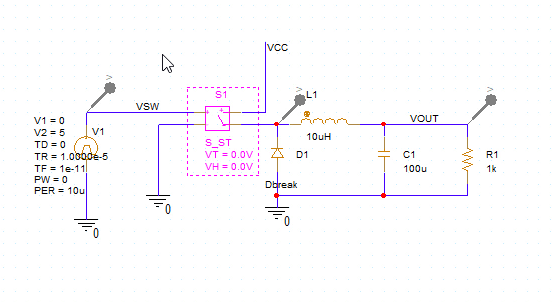
Step 9: Click to place the switch in the schematic.
Running the Simulation
Step 10: Select PSpice > Run from the menu.
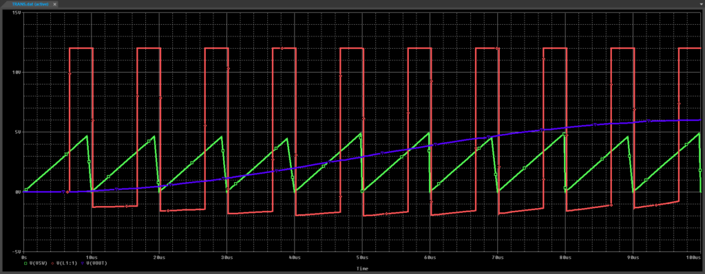
Step 11: View the simulation results.
Note: In this example, the green V(VSW) trace shows the voltage at the switch control node. The red V(L1:1) trace shows the voltage at the buck converter input. The purple-blue trace shows the converter output voltage.
Modifying the Switch
Step 12: Back in the schematic, right-click the switch and select More > Edit PSpice Component.
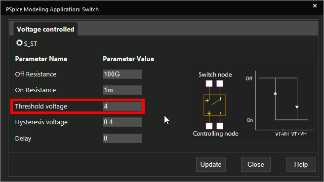
Step 13: Change the Threshold Voltage to 4 and click Update.
Step 14: Select PSpice > Run from the menu again.
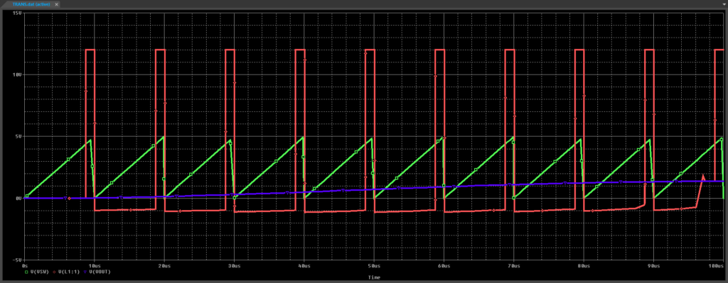
Step 15: View the simulation results. The pulse duty cycle has been reduced now that the switch turns on at a higher voltage.
Wrap Up and Next Steps
Quickly create the required switch SPICE model and simulate accurate circuit behavior with the Modeling Application in OrCAD PSpice. Test out this feature and more with a free trial of OrCAD. To learn more about determining the required parameters for a switch SPICE Model in your circuit designs, view our blog here.

