Every SPICE simulation needs to have an accurate source or input signal. The sine source, producing a voltage that varies as a sine wave with time, is fundamental in all types of signal analyses, especially in AC sweep and frequency-response. PSpice allows you to quickly create the required Sine source SPICE model for a realistic simulation by easily defining the type and signal value.
This quick how-to will provide step-by-step instructions on how to create a sine source SPICE model in OrCAD PSpice.
To follow along, download the provided files above the table of contents.
How-to Video

Creating a Sine Source
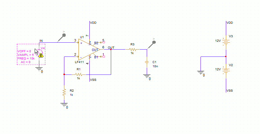
Step 1: Open the provided design in OrCAD PSpice Designer.
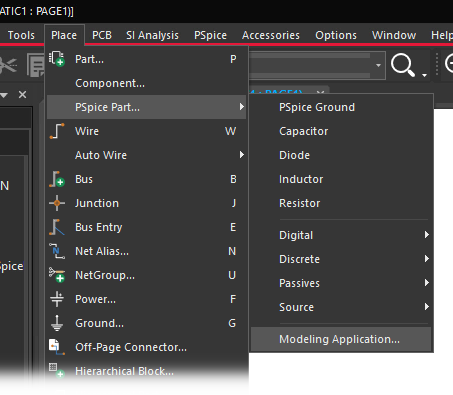
Step 2: Select Place > PSpice Part > Modeling Application from the menu.
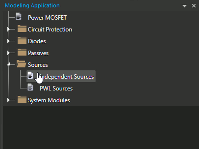
Step 3: In the Modeling application, expand Sources and select Independent Sources.
Step 4: The Independent Sources window opens. Select the Sine tab.
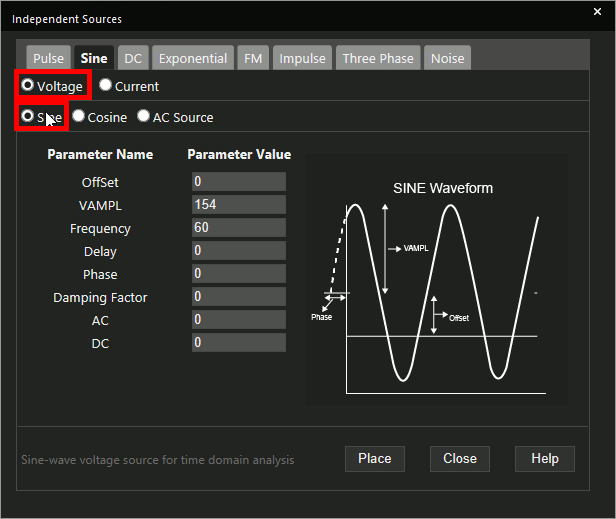
Step 5: Select Voltage as the source type and Sine as the waveform type.
Note: Select AC Source to define a source in the frequency domain for AC Sweep analysis.
Step 6: Enter 5 for VAMPL for an amplitude of 5V.
Step 7: Enter 10k for the Frequency.
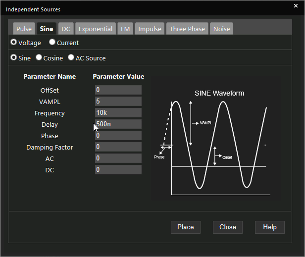
Step 8: Enter 500n for the delay.
Note: The sine wave will begin 500nsec after the simulation starts. Other configurable parameters include:
- Phase
- Damping factor (if the signal is to decay)
- AC/DC amplitude for an AC Sweep, Bias Point, or Transient analysis
Learn how to determine the required parameters for a Sine source SPICE Model here.
Step 9: Click Place.
Step 10: Click to place the source in the schematic.
Running the Simulation
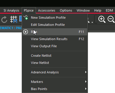
Step 11: Select PSpice > Run from the menu.
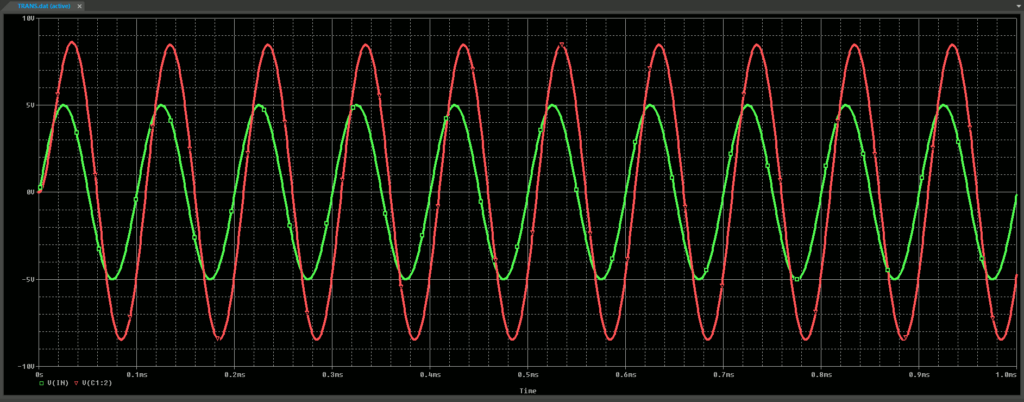
Step 12: View the simulation results. A sine wave was generated at the input and output of the circuit.
Adding Damping
Step 13: Back in the schematic, select the source, then right-click and select More > Edit Source Component.
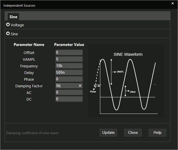
Step 14: Enter 5k for the Damping Factor and click Update.
Step 15: Select PSpice > Run from the menu.
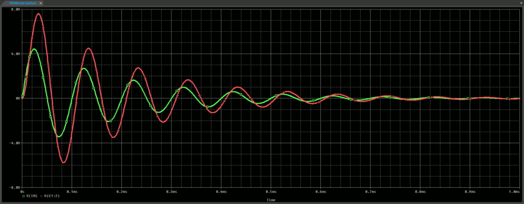
Step 16: View the simulation results. Both sine waves now decay to near zero by the end of the simulation.
Wrap Up and Next Steps
Quickly create the required sine source and simulate accurate circuit behavior with Sine Source SPICE models in OrCAD PSpice. Test out this feature and more with a free trial of OrCAD. To learn more about determining the required parameters for a Sine source SPICE Model in your circuit designs, view our blog here.
