Every SPICE simulation needs to have an accurate source or input signal for a realistic analysis. PSpice allows you to quickly define and create the required pulse source SPICE model for a realistic simulation.
This quick how-to will provide step-by-step instructions on how to create a Pulse Source SPICE model in OrCAD PSpice.
To follow along, download the files provided above the table of contents.
How-To Video

Defining a Pulse Source
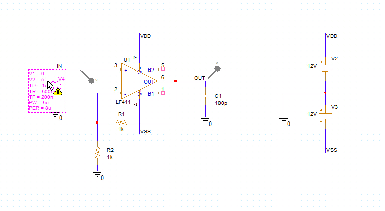
Step 1: Open the provided design in OrCAD PSpice Designer.
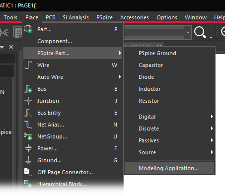
Step 2: Select Place > PSpice Part > Modeling Application from the menu.
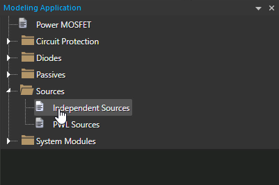
Step 3: In the Modeling Application, expand Sources and select Independent Sources.
Step 4: The Independent Sources window opens. Select the Pulse tab.
Step 5: Select Voltage to create a voltage pulse.
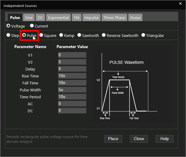
Step 6: Select Pulse as the waveform type.
Step 7: Enter 0 for V1 (low voltage) and 5 for V2 (high voltage).
Step 8: Enter 8u for the pulse time period.
Step 9: Enter 1u for the pulse delay.
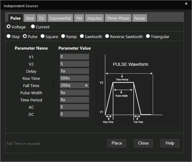
Step 10: Enter 500n for the rise time and 200n for the fall time.
Note: The rise time determines the time it takes for the pulse to switch from V1 to V2, and the fall time determines the time it takes for the switch from V2 to V1. Additional options are available to define pulse width, and AC or DC offset.
Learn how to determine the required parameters for a pulse source SPICE Model here.
Step 11: Click Place to place the source.
Step 12: Click to place the source in the schematic.
Running the Simulation
Step 13: Select PSpice > Run from the menu.
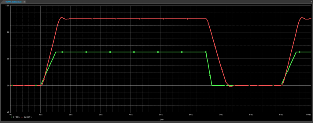
Step 14: View the simulation results. A series of pulses are generated at a period of eight microseconds.
Modifying Pulse Parameters
Step 15: Back in the schematic, select the source, right-click and select More > Edit Source Component to re-open the source configuration window.
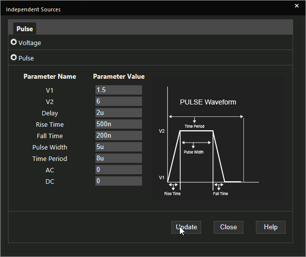
Step 16: Change V1 to 1.5, V2 to 6, and the delay to 2u. Click Update.
Step 17: Select PSpice > Run from the menu.
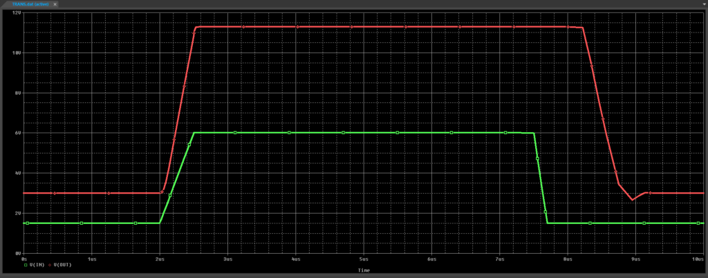
Step 18: View the simulation results. The input and output pulses have shifted upwards.
Wrap Up and Next Steps
Quickly create the required PWL source and simulate accurate circuit behavior with Pulse Source SPICE models in OrCAD PSpice. Test out this feature and more with a free trial of OrCAD. To learn more about determining the required parameters for a pulse source SPICE Model in your circuit designs, view our blog here.

