Every SPICE simulation needs to have an accurate source or input signal for a realistic analysis. Certain circuits, such as video processing, may require a source that does not follow a typical mathematical model. PSpice allows you to quickly define and create the required Piecewise Linear (PWL) source SPICE model for a realistic simulation.
This quick how-to will provide step-by-step instructions on how to create a Piecewise Linear source SPICE model in OrCAD PSpice.
To follow along, download the provided files above the table of contents.
How-To Video

Defining a PWL Source Manually
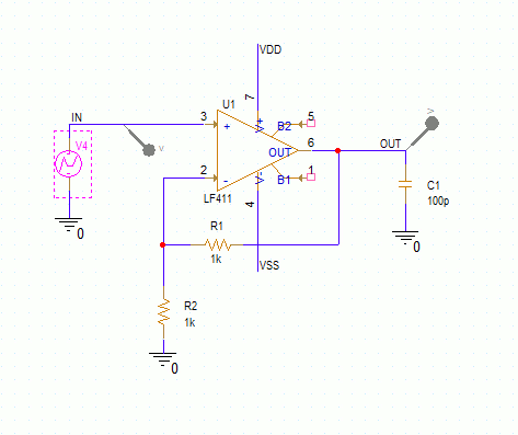
Step 1: Open the provided design in OrCAD PSpice Designer.
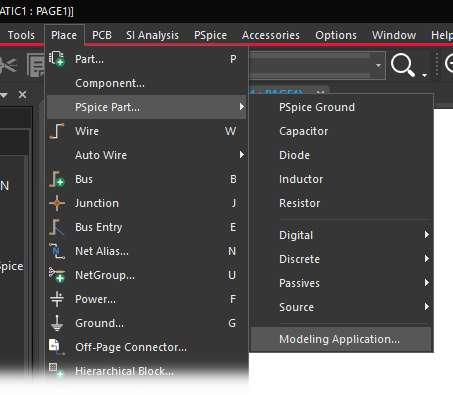
Step 2: Select Place > PSpice Part > Modeling Application from the menu.
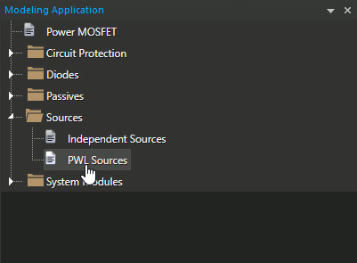
Step 3: In the Modeling Application, expand Sources and select PWL Sources.
Step 4: The Piecewise Linear (PWL) Sources window opens. Select Voltage PWL to create a voltage source.
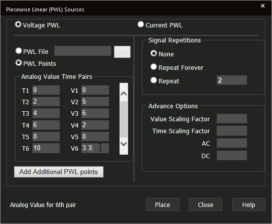
Step 5: Enter the values shown above for Analog Value Time Pairs.
Step 6: Select Repeat Forever under Signal Repetitions.
Note: This will run the PWL signal throughout the entire simulation. Options are available to run the signal once and a fixed number of times.
Learn how to determine the required parameters for a PWL SPICE Model here.
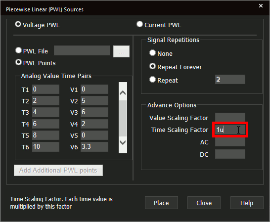
Step 7: Under Advance Options, enter 1u into the Time Scaling Factor field.
Note: This will multiply all defined time values by 1 microsecond, so you don’t have to manually define the unit for each value. Similarly, the value can be scaled. Options also exist for adding an AC or DC component.
Step 8: Click Place to attach the source to your cursor.
Step 9: Click to place the source in the schematic.
Running the Simulation
Step 10: Select PSpice > Run from the menu.
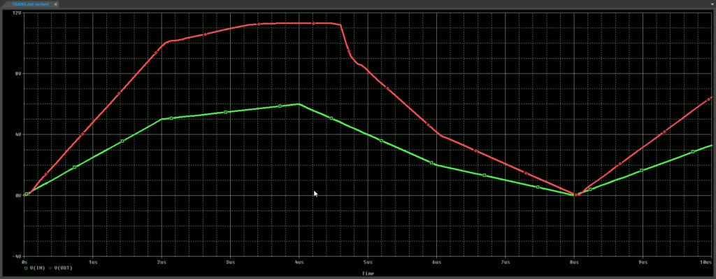
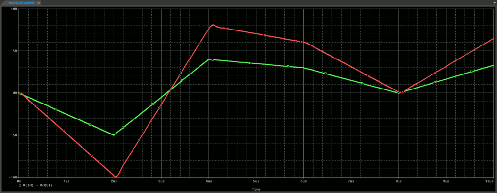
Step 11: View the simulation results. The input voltage matches the values defined in step 5.
Defining a PWL Source from Text
Step 12: A PWL source can be defined in a text file as well. Open the working directory in File Explorer.
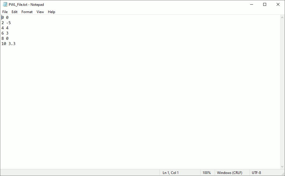
Step 13: Open the provided file, PWL_File.txt, in a text editor such as Notepad. The values are listed with time on the left and voltage (or current) on the right. Close the text editor.
Step 14: Back in Capture, right-click the PWL source and select More > Edit Source Component to re-open the Piecewise Linear Sources window.
Step 15: Select PWL File above the Analog Value Time Pairs list.
Step 16: Select the ellipsis to load in a file.
Step 17: Browse to the location of PWL_File.txt, select the file, and click Open.
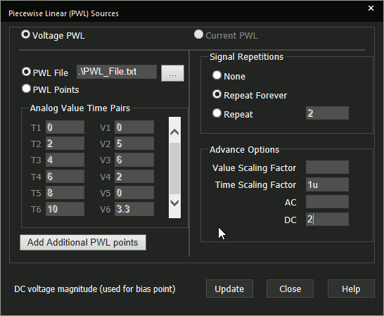
Step 18: Under Advance Options, enter 2 in the DC field to add a 2V DC offset.
Step 19: Select Update.
Step 20: Select PSpice > Run from the menu.
Step 21: View the simulation results. The input voltage matches the values defined in the text file plus 2V.
Wrap Up and Next Steps
Quickly create the required PWL source and simulate accurate circuit behavior with PWL Source SPICE models in OrCAD PSpice. Test out this feature and more with a free trial of OrCAD. To learn more about determining the required parameters for a PWL SPICE Model in your circuit designs, view our blog here.
