In an ideal world, the only significant property of a resistor should be its resistance. However, real resistors will always have some parasitic inductance and shunt capacitance, especially if they are meant for higher power. Not taking this into account and only simulating an ideal resistor may lead to unexpected and undesired circuit behavior. PSpice allows you to quickly place and create a non-ideal resistor model for a realistic simulation.
This quick how-to will provide step-by-step instructions on how to create and simulate a non-ideal resistor model with the Model Editor in OrCAD PSpice.
To follow along, download the provided files above the table of contents.
How-To Video
 Open in New Window
Running an Ideal Simulation
Step 1: Open the provided design in OrCAD PSpice Designer.
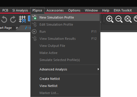
Step 2: Select PSpice > New Simulation Profile from the menu.
Step 3: Name the profile AC_Trans and click Create.
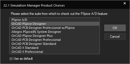
Note: You may be prompted to select a license from which to check out the PSpice A/D feature. Select the appropriate license and click OK.
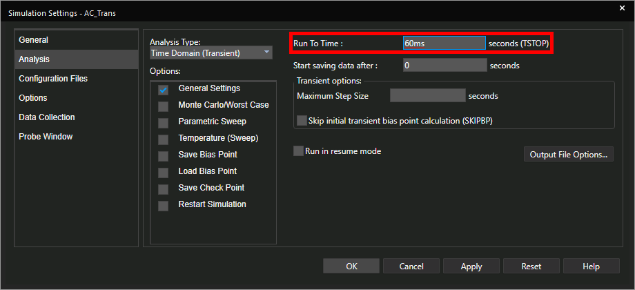
Step 4: Set the Run To Time to 60ms. Leave the other settings as the defaults and click OK.
Step 5: Select the Voltage/Level Marker button from the toolbar.
Step 6: Click to place a probe on the AC1 net.
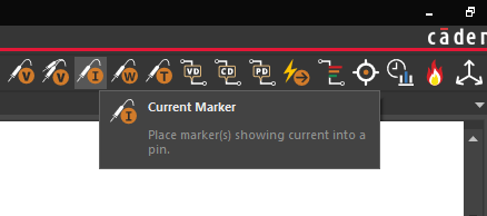
Step 7: Select the Current Marker button from the toolbar.
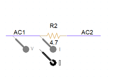
Step 8: Click to place a probe on the pin of R2 connected to AC1. Right-click and select End Mode.
Step 9: Select PSpice > Run from the menu.
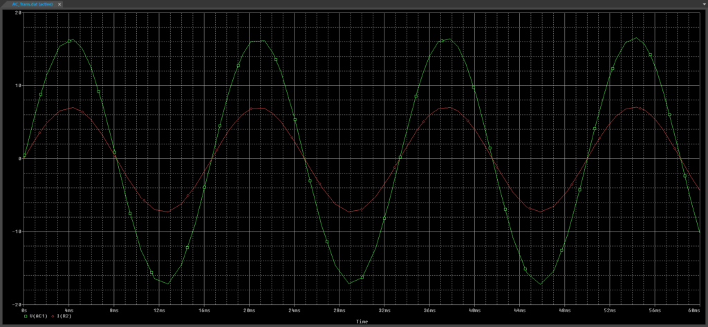
Step 10: View the simulation results. The resistor voltage and current are in phase, as expected.
Create a Non-Ideal Resistor Model
Step 11: Back in the schematic, select ideal resistor R2 and press Delete on the keyboard.
Step 12: Select Place > Component from the menu.
Step 13: The Unified CIS tab opens. Expand PSpice from the Categories list.
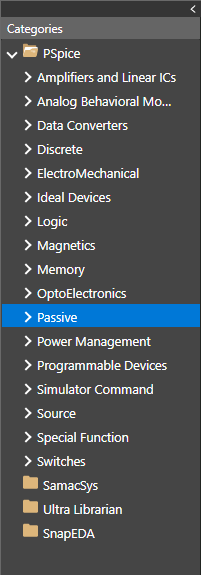
Step 14: Select Passive.
Step 15: Enter awbresistor into the Search field and click the Search button.
Note: The “awbresistor” is a resistor model that contains parasitics and is pre-configured for advanced analysis in PSpice.
Step 16: Right-click the awbresistor component and select Place.
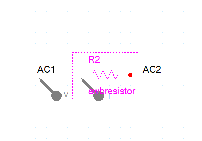
Step 17: Click to place the resistor in the space left by R2. Right-click and select End Mode.
Step 18: Select PSpice > Run from the menu.
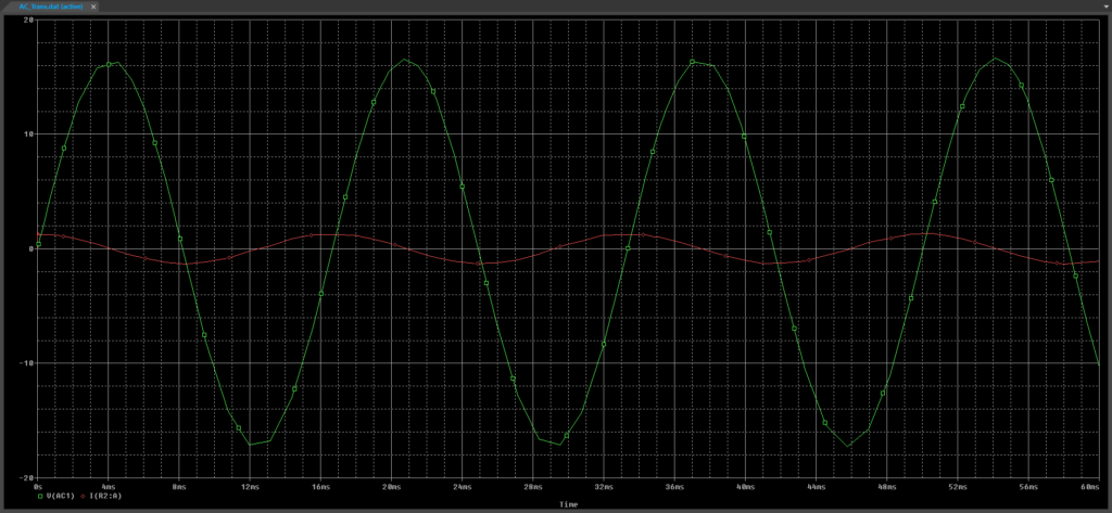
Step 19: View the simulation results. The current has decreased and now leads the voltage.
Note: This resistor now has inductive and capacitive properties, which are causing the phase shift.
Adjusting the Resistor Parameters
Step 20: Right-click the resistor and select Edit PSpice Model.
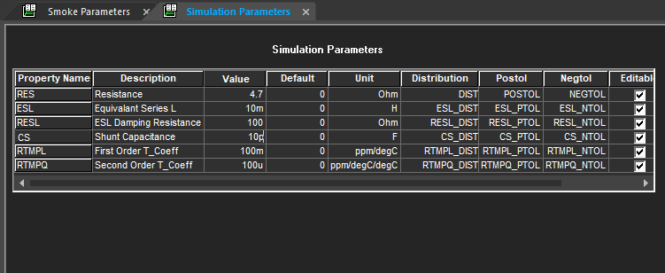
Step 21: The PSpice Model Editor opens with a table of simulation parameters. Assign the following property values:
- RES: 4.7
- ESL: 10m
- CS: 10p
Step 22: Select File > Save from the menu. Close the PSpice Model Editor.
Step 23: Right-click the resistor and select Associate PSpice Model.
Note: The PSpice model must be re-assigned to the component after it is edited.
Step 24: You will be prompted that the design must be saved prior to association. Click Yes.
Step 25: You will be prompted that the current PSpice model will be overwritten. Click Yes.
Step 26: The Associate PSpice Model window opens. Click Browse to browse for the library.
Step 27: Browse to the location of the Step_Down_Trans-PSpiceFiles folder provided in the materials. Select the file STEP_DOWN_TRANS.lib and click Open.
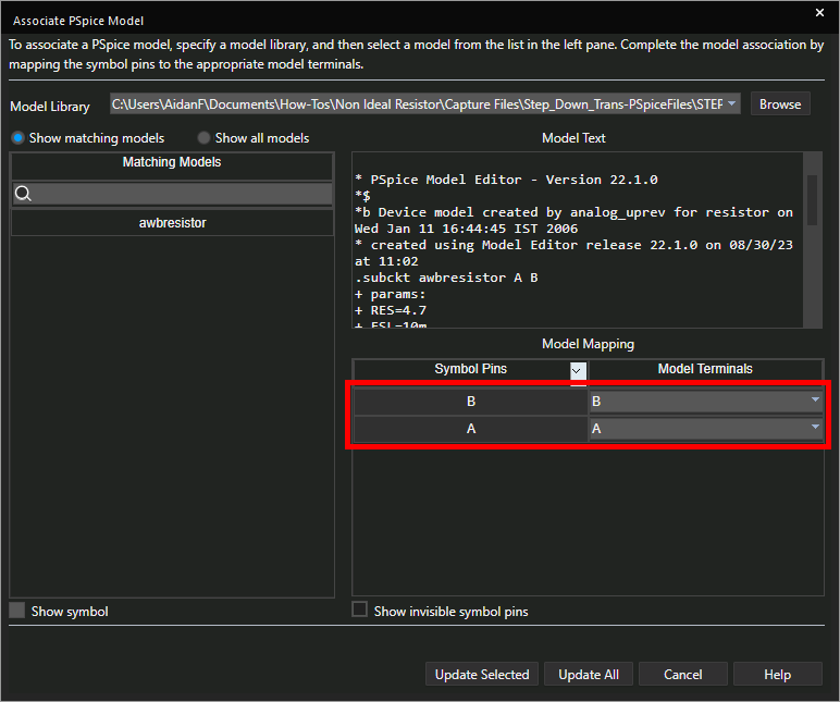
Step 28: In the Model Mapping table, confirm that symbol pins B and A match with model terminals B and A respectively.
Note: The model text containing the SPICE code can be previewed in this window.
Step 29: Click Update Selected to update the resistor.
Step 30: An info message will appear, indicating that the model was attached successfully. Click OK.
Step 31: Select PSpice > Run from the menu.
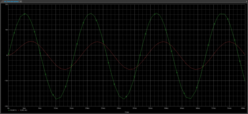
Step 32: View the results. The current now lags the voltage due to the increased inductive reactance and peaks closer to that of the ideal resistor due to the decreased resistance.
Wrap Up & Next Steps
Quickly create a non-ideal resistor model required for accurate SPICE simulations with OrCAD PSpice. View other how-tos for step-by-step instructions on quickly creating non-ideal capacitors and non-ideal inductors using the Modeling Application in PSpice. Test out this feature and more with a free trial of OrCAD.

