Modern electronics could not exist without semiconductors and digital electronics but as electronics become faster and more complex, it’s essential to model realistic behavior to ensure design accuracy. To realistically simulate and analyze the functionality of digital circuits which include gates, flip-flops, and latches, an accurate digital source must be incorporated. Create a digital stimulus SPICE model to generate input signals that emulate the behavior of digital logic levels through a sequence of binary states (logic 0 and 1) based on specified timing and waveform characteristics. PSpice allows you to quickly create a digital stimulus SPICE model for accurate simulation of digital designs with a wizard-based approach.
This quick how-to will provide step-by-step instructions on how to create a digital stimulus SPICE model in PSpice using the Modeling Application.
To follow along, download the provided files above the table of contents.
How-To Video
 Open in New Window
Create a Digital Stimulus SPICE Model
Step 1: Open the provided design in PSpice 23.1 or above.
Note: A wizard-based approach to digital models is new in version 23.1. See other new features here.
Step 2: Select Place > PSpice Part > Modeling Application from the menu.
Step 3: In the Modeling Application, expand Sources.
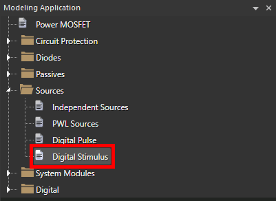
Step 4: Select Digital Stimulus.
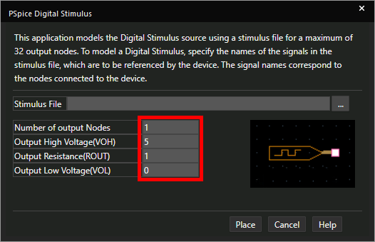
Step 5: The Digital Stimulus options window opens. Enter the following model parameters:
- Number of Output Nodes: 1
- Output High Voltage: 5
- Output Resistance: 1
- Output Low Voltage: 0
Note: Learn how to design a realistic digital stimulus here.
Step 6: A digital stimulus SPICE model typically emulates a specific sequence of bits and therefore a text file is used to define the source. Select the ellipsis for Stimulus File to load in a file.
Note: The text file starts with the name of the signal as its header and consists of time stamps and the signal output at each time in tabular form.
Step 7: Browse to and select the provided D_ST_CLK.stl file. Click Open.
Step 8: Click Place.
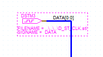
Step 9: Click to place the stimulus on the bus in the schematic.
Note: A digital stimulus can have one or multiple outputs and must be placed on a bus.
Step 10: Select the Voltage/Level Marker button from the toolbar.
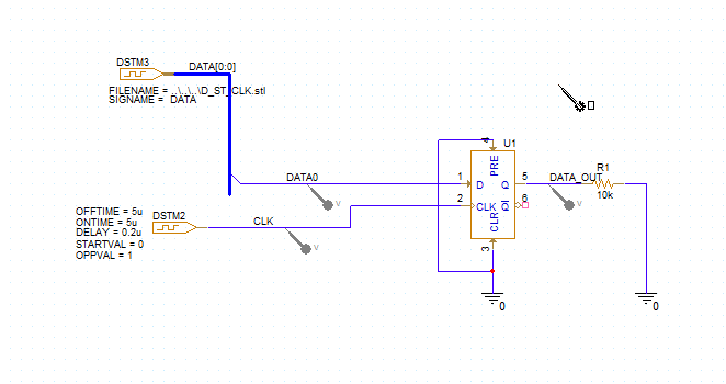
Step 11: Click to place probes on the CLK, DATA0, and DATA_OUT nets. Right-click and select End Mode when finished.
Running the Simulation
Step 12: Select PSpice > Run from the menu.
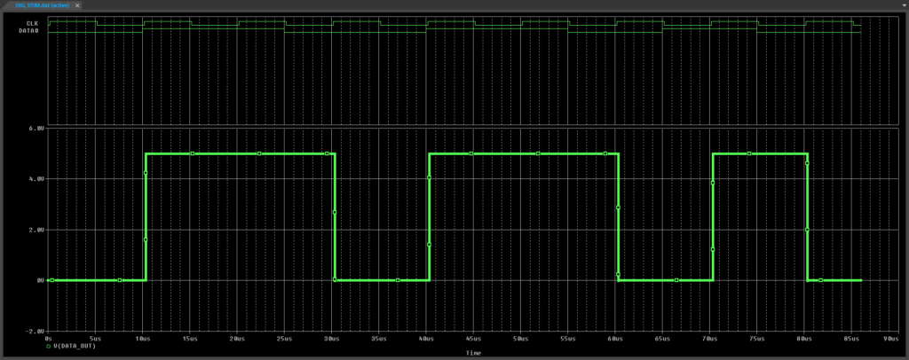
Step 13: View the simulation results. The output follows the input at each rising clock edge.
Step 14: Close the PSpice A/D window.
Modifying the Digital Stimulus SPICE Model
Step 15: Open File Explorer and browse to the working directory.
Step 16: Right-click the D_ST_CLK.stl file and select Open With. Open the file in a text editor such as Notepad.
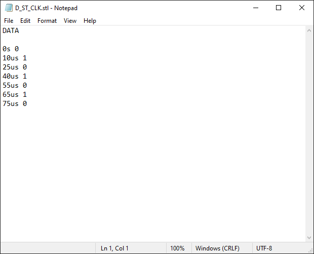
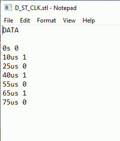
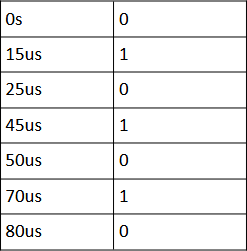
Note: The stimulus file header contains the name of each signal. Below the header is a table showing the binary value of the signal at each time stamp.
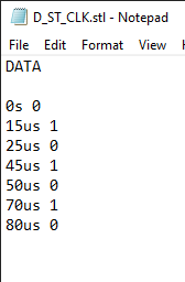
Step 17: Adjust the time stamps such that the table appears as shown below.
Step 18: Back in Capture, select PSpice > Run from the menu.
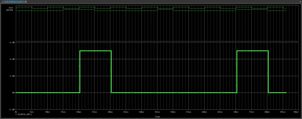
Step 19: View the simulation results. The stimulus pulses and flip-flop output have been adjusted.
Wrap Up & Next Steps
Quickly create a digital stimulus SPICE model to accurately analyze your digital circuits with the PSpice Modeling Application. Upgrade to the latest 23.1 release or test out this feature and more with a free trial of OrCAD.

