The first step to creating a new PCB design is to create the board outline. With design form factors becoming smaller and more complex, it is essential to accurately create the board outline. OrCAD X Presto includes multiple methods to create a design outline, such as drawing and importing.
This quick how-to will provide step-by-step instructions on how to create a board outline in OrCAD X Presto.
How-To Video
 Open in New Window
Create a Design Outline in OrCAD X Presto
Step 1: Open a blank PCB design in OrCAD X Presto.
Step 2: Select ECO > Draw Design Outline from the menu.
Step 3: The Design Outline widget opens. Select Rectangle.
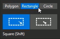
Note: Options include to draw the rectangle corner to corner or center to corner. Hold Shift to draw a square.
Step 4: Select Circle in the Design Outline widget.
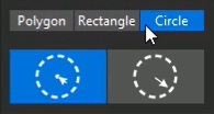
Note: Options include to draw the circle radius or diameter.
Step 5: Select Polygon in the Design Outline widget.
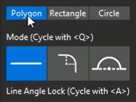
Note: Options include to draw lines, arcs, or indent arcs. Cycle through the desired mode while drawing with Q on the keyboard.

Step 6: Click to start drawing the outline. A heads-up display shows the length and angle for each segment.
Step 7: Click to place a point, then press Q on the keyboard twice to select the indented arc mode.
Note: Use A on the keyboard to lock the arc angle and use C to change direction.
Step 8: Click to place an indented arc. Press Q again to return to line mode.

Step 9: Continue drawing the outline. Use A on the keyboard to lock the line angle.
Note: Alignment guides appear when you are close to another vertex or line.
Step 10: Click the starting vertex to close the shape. The conductor and component keepins are automatically drawn and the outline is automatically selected.
Adjusting the Outline
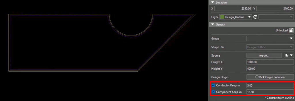
Step 11: In the Properties panel, enter 5 for the conductor keep-in value. The conductor keep-in is moved closer to the edge of the board.
Step 12: Enter 12 for the component keep-in value.
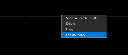
Step 13: To change the boundary of the design outline, right-click and select Edit Boundary. Click to modify the boundary as desired. The board will be automatically cut and filled in.
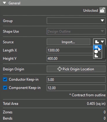
Step 14: In the Properties panel, under Source, select the rectangle from the drop-down menu to change the outline to a rectangle.
Note: This will erase the custom polygon.
Importing a Board Outline
Step 15: Select Import under source to import a mechanical drawing for the board outline.
Step 16: Browse to the desired .idx or .bsm file, select the file, and click Open.
Step 17: Alternatively, to import a mechanical drawing, open the ECO menu to view other file format options, including .dxf and MCADX. Select IDX Import.
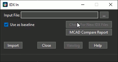
Step 18: The IDX In window opens. Here you can configure settings for the design import. Click Close to close the window
Note: Here you can select the input file, whether to use the mechanical import as the board outline and generate a comparison report.
Wrap Up & Next Steps
Quickly create a design outline in OrCAD X Presto with drawing and importing to accurately define the extents of the PCB design. Test out this feature and more with a free trial of OrCAD X Presto. For more how-tos and step-by-step walk-throughs, visit EMA Academy.