Simulating real-world conditions in your SPICE simulations is critical to obtain a realistic analysis and first-pass design success; this includes considering circuit response to noise. Performing noise analysis is an important part of simulation to ensure that a circuit can perform as intended in real-world conditions. However, if a noise analysis fails, a good troubleshooting step is to isolate which components are contributing the most noise. PSpice allows designers to control noise contributions from any component in the circuit to help identify and correct sources of noise.
This quick how-to will provide step-by-step instructions on how to control noise contributions from specific components in PSpice.
To follow along, download the provided files above the table of contents.
How-To Video
 Open in New Window
Create a Noise Analysis Simulation
Step 1: Open the provided design in PSpice Designer.
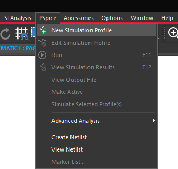
Step 2: Select PSpice > New Simulation Profile and click OK.
Step 3: Name the simulation profile AC_Noise_Analysis and click Create.
Note: If the Simulation Manager Product Choices window opens, select the appropriate license and click OK.
Step 4: The Simulation Settings window opens. Select AC Sweep/Noise from the Analysis Type drop-down menu.
Step 5: Enter 1MEG for the Start Frequency, 1G for the End Frequency, and set the Points/Decade to 10.
Step 6: Select Enabled under Noise Analysis to activate Noise Analysis.
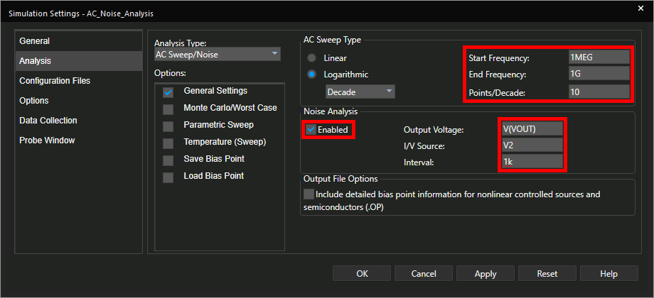
Step 7: Enter V(VOUT) for the Output Voltage, V2 for the I/V Source, and 1k for the Interval.
Note: The Output Voltage defines the node where the noise output is measured. The I/V source defines the name of the source where equivalent input noise is calculated. The Interval defines how often the noise analysis data is written to the output file.
Step 8: Click OK to save the settings and close the window.
Step 9: Select the Voltage/Level Marker button from the toolbar.
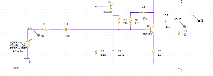
Step 10: Click to place probes at the VIN and VOUT nets. Right-click and select End Mode.
Run the Simulation
Step 11: Select PSpice > Run from the menu.
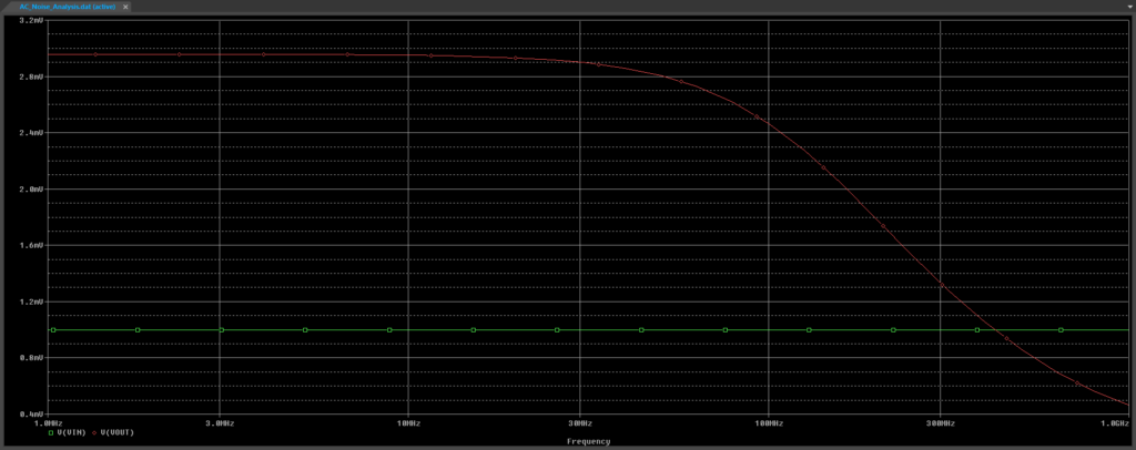
Step 12: View the simulation results. The signal output is plotted as a low-pass amplifier. We will now change the parameters to view the noise output.
Create a Noise Analysis Output
Step 13: Double-click V(VOUT) in the legend at the bottom of the plot.
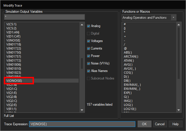
Step 14: The Modify Trace window opens. Select V(ONOISE) from the Simulation Output Variables list and click OK.
Step 15: Double-click V(VIN) in the legend at the bottom of the plot.
Step 16: Select V(INOISE) from the Simulation Output Variables list and click OK.
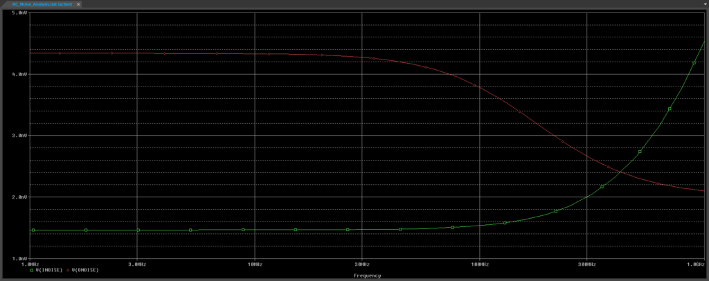
Step 17: View the plot. The input noise amplitude rises at higher frequencies and the output noise curve looks about the same as the output signal curve.
Save Plot Configurations
Note: The plotted curves can be saved and shown the next time the simulation is run to reuse settings and save time with analysis setup.
Step 18: Select Simulation > Edit Profile from the menu.
Step 19: The Simulation Settings window opens. Select Probe Window from the list on the left.
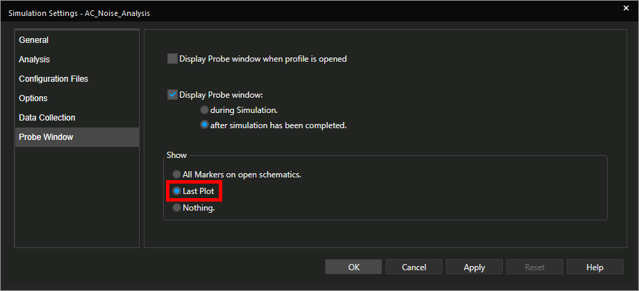
Step 20: Select Last Plot under Show and click OK. The next time the simulation is run, the noise plot will be shown.
View the Top Noise Contributors
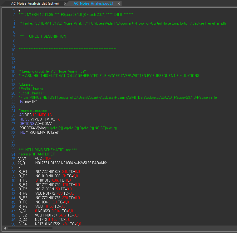
Step 21: Select View > Output File from the menu to view the simulation report. This report shows a simulation log including model parameters, node voltages, power dissipation, and top contributors to noise.
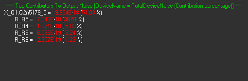
Step 22: Scroll to the section for Top Contributors to Output Noise. Transistor Q1 is listed as the top contributor. In the next steps, we will modify Q1 such that its noise contributions are not counted.
Step 23: Close the PSpice A/D window.
Control Noise Contributions in PSpice
Step 24: Back in the schematic, select transistor Q1. Right-click and select Edit Properties.
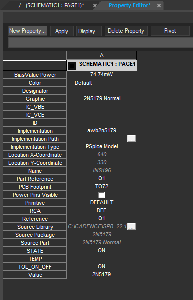
Step 25: The Property Editor window opens. Select New Property.
Step 26: To control the noise contributions associated with Q1, in the Add New Property window, enter NOISELESS for the name and Yes for the value. Click OK to add the property.
Step 27: Click Apply and close the Property Editor tab.
Check the Simulation
Step 28: Select PSpice > Run from the menu to run the simulation.
Step 29. View the simulation results. The input and output are mostly the same.
Step 30: Select View > Output File from the menu.
Step 31: Scroll to the section for Top Contributors to Output Noise.
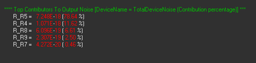
Step 32: View the contributor list. Noise from Q1 is being ignored, so Q1 is no longer listed. R5 is now the highest noise contributor.
Wrap Up & Next Steps
Control noise contributions to quickly isolate noise-contributing components and ensure your design performs as intended with PSpice. Upgrade to the latest 23.1 release or test out this feature and more with a free trial of OrCAD.
