With today’s designs shrinking and becoming more complex simultaneously, high-density routing has become common in the PCB design industry. Every PCB manufacturer has different rules and requirements for high-density features making it difficult to configure HDI routing with:
- Microvias
- Via/pad spacing
- Blind/buried vias
Designing a board unaware of these rules can lead to several redesigns, increasing price and using significant design time. OrCAD X Presto has several options available to define constraints for high-density boards to ensure the design remains on time and under budget.
This quick how-to will provide step-by-step instructions on how to configure HDI routing including rules, constraints, and vias in OrCAD X Presto Professional.
How-To Video
Configure HDI Routing Constraints: Via Stacking
Step 1: Open a design in OrCAD X Presto.
Note: HDI constraints may be required if microvias smaller than the standard drilled vias are used in the design. It is recommended to configure these constraints before routing.
Step 2: Select Tools > Constraint Manager from the menu.
Step 3: In the Constraint Manager window, navigate to the Physical > Physical Constraint Set > All Layers worksheet.
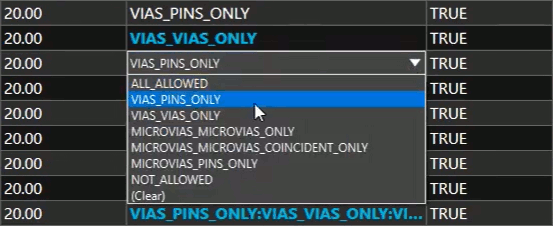
Step 4: In the Pad-Pad connect column, select the desired via connection rule for each layer.
Note: This determines the type of connections allowed for pins/vias whose connection points lie within the extents of other pins/vias. Available options include:
- ALL_ALLOWED: Any type of direct connection allowed.
- VIAS_PINS_ONLY: Only pin-via direct connections can be formed.
- VIAS_VIAS_ONLY: Only via-via direct connections can be formed.
- MICROVIAS_MICROVIAS_ONLY: Only microvia-microvia connections can be formed.
- MICROVIAS_MICROVIAS_COINCIDENT_ONLY: Only microvia-microvia connections can be formed if the vias are coincident.
- MICROVIAS_PINS_ONLY: Only microvia-pin direct connections can be formed.
- NOT_ALLOWED: Direct connections cannot be formed.
Multiple constraint sets can be created for different nets.
Configure HDI Routing Constraints: Net Spacing
Note: Same-net spacing constraints should be defined for microvias for HDI routing.
Step 5: Select the Same Net Spacing > Net > All Layers worksheet from the Worksheet Selector panel.
Step 6: View the Referenced Same Net Spacing CSet column.
Note: Each net is assigned a Same Net Spacing CSet. Need help configuring constraints and constraint sets? View our free workshop here.

Step 7: Scroll to the right to view the Microvia To section. Configure the Same Net spacing rules required for your design.
Note: A negative number (-1.0) here allows for the same-net via pads to overlap and will default to the hole-to-hole spacing constraint values.
Step 8: Close the Constraint Manager.
HDI Routing in OrCAD X Presto
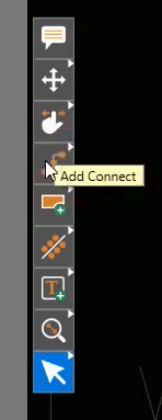
Step 9: Back in the PCB canvas, select the Add Connect mode from the toolbar.
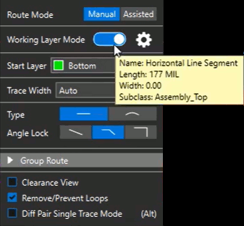
Step 10: In the Routing widget, enable Working Layer Mode.
Note: This will allow you to choose blind/buried vias and routing layers as needed. Adding a via with this option off will create the default via.
Click the gear icon to open a settings window. Here you can configure which layers can be selected when adding a via.
Step 11: Click a net to start routing.
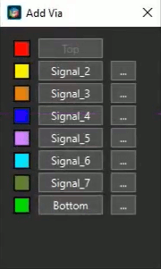
Step 12: Double-click to view the Add Via window to create a via.
Step 13: Select an adjacent layer, such as Signal 2, to start routing on that layer.
Note: These layers will vary based on your design.
Step 14: Double-click to add another via. Select Signal 3
Step 15: Select Bottom. The vias are automatically attached to the cursor and the distances are automatically defined based on the configured constraints.
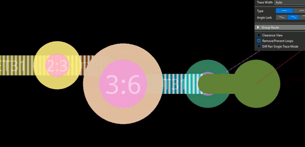
Note: The minimum and maximum BB Via Stagger options can be set in the Constraint Manager to define how far individual via stackups need to be from each other.
Step 16: Press Backspace on the keyboard repeatedly until the placed vias are removed and the top layer is re-attached to the cursor.
Step 17: Double-click and select Bottom. The first Signal 2 microvia is attached to the cursor.
Step 18: Click to place each via to cascade to the bottom layer.
Configuring Available Vias
Note: The available vias to use in the design can be configured in the Constraint Manager as well.
Step 19: Select Tools > Constraint Manager toreturn to the Constraint Manager.
Step 20: Select the Physical > Physical Constraint Set > All Layers worksheet.
Step 21: Double-click a cell in the Vias column to open the Edit Via List window.
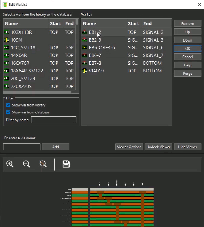
Step 22: The window opens with a list of available vias to use in the constraint set. Double-click a via from the list of available vias to add it to the selected layer. Click OK to save the settings and close the window when finished.
Note: The start and end layers of each available via or microvia are shown in the via list. If multiple through-board vias are listed, they can be selected during routing. Via priority can be adjusted with the Up and Down buttons.
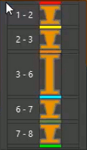
A cross section view is shown at the bottom of the window.
Step 23: Close the Constraint Manager.
Creating a Stacked Via
Step 24: Click to start routing another net with no stagger requirement. Double-click to add a via.
Step 25: The Add Via window opens. Select the most opposite layer. For example, if routing on the top, select Bottom.
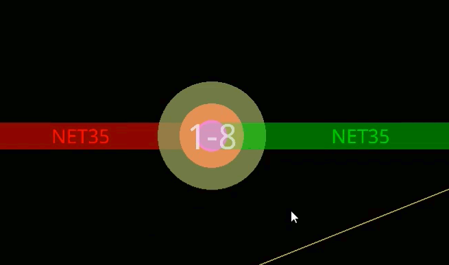
Step 26: A singular via stack is added. This stack contains the same microvias used to create the cascading stack, all in the same location.
Adding Overlapping Vias
Step 27: Click to start routing another net with a negative defined Microvia To distance.
Step 28: Double-click and select Bottom.

Step 29: Click to place each via to cascade to the bottom layer. The vias overlap, as the Microvia To distance is negative.
Splitting Via Stacks
Step 30: Select the Slide mode from the toolbar.
Step 31: Click the stacked via to slide it. The via is moved as one unit.
Step 32: While still sliding the via, right-click and select Split Stack.
Step 33: A new widget opens, showing each stackup available. Click to select the desired stackup or click and hold the left mouse button to select multiple stackups.

Step 34: The selected via stackup is attached to your cursor. Click to place the vias.
Wrap Up & Next Steps
Quickly and easily configure HDI routing rules and constraints in OrCAD X Presto. Don’t have OrCAD X Presto? Get your free trial here; and for more step-by step instructions and walk-throughs on using OrCAD X Presto, visit EMA Academy.
