Circuit simulations are often performed with ideal conditions; however, circuits rarely operate this way in the field due to external factors such as noise and temperature variations. These external influences can negatively affect circuit behavior, for example if a component gets hot enough, its value may be skewed, and the ideal simulation results will no longer apply. While temperature sweeps can be performed in PSpice to view the effects of temperature on steady-state circuit behavior, new in PSpice Designer 23.1 is the ability to configure a breakout model to quickly and easily model temperature variations in a single SPICE simulation. Designers can configure a breakout model to:
- Customize component parameters for simulations
- Set up Monte Carlo and worst-case analyses with device and/or lot tolerances specified for individual model parameters
- Simulate the effects of a component heating up over time
- Obtain a realistic time-domain simulation
This quick how-to will provide step-by-step instructions on how to configure a breakout model to simulate temperature variations over time in PSpice.
To follow along, download the provided files above the table of contents.
How-To Video
 Open in New Window
Place a Breakout Model in PSpice
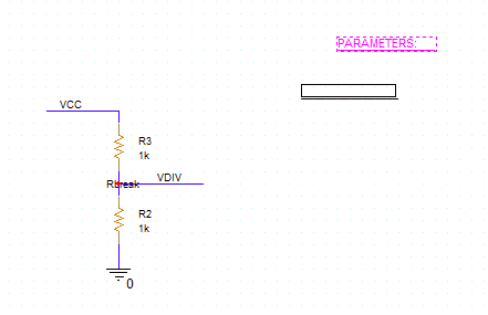
Step 1: Open the provided design in PSpice Designer.
Step 2: Select resistor R1 and press Delete on the keyboard to remove it.
Step 3: Select Place > Component from the menu to open the Component Explorer tab.
Step 4: In the PSpice category, expand and select Passive > Resistor.
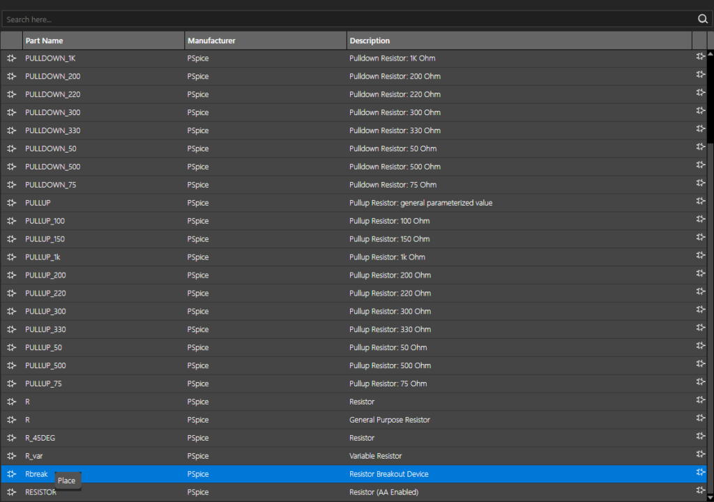
Step 5: Select Rbreak at the bottom of the list. Right-click and select Place.
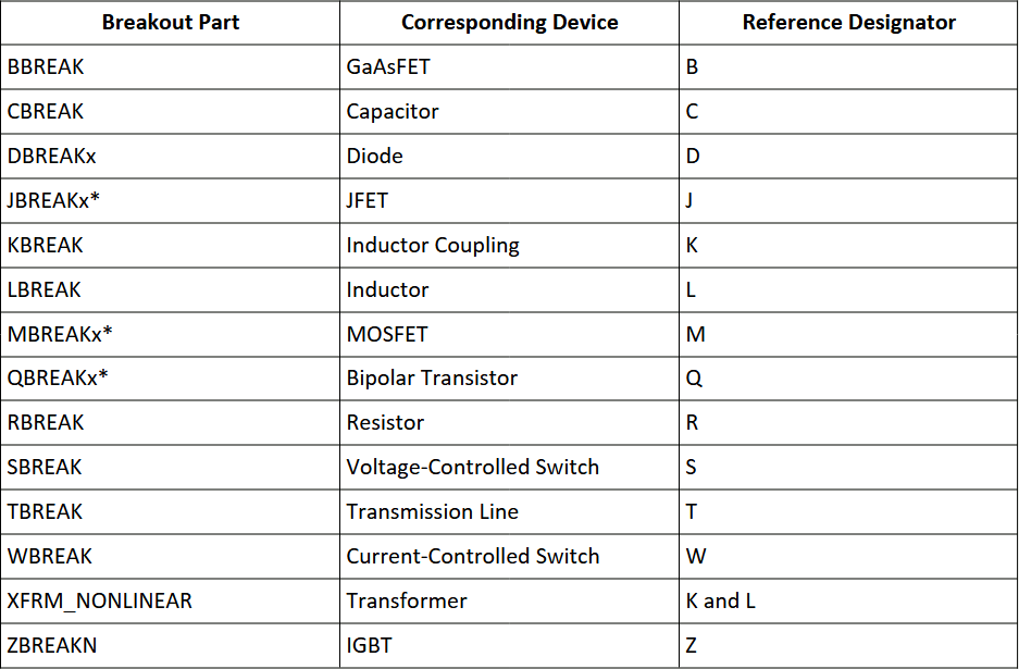
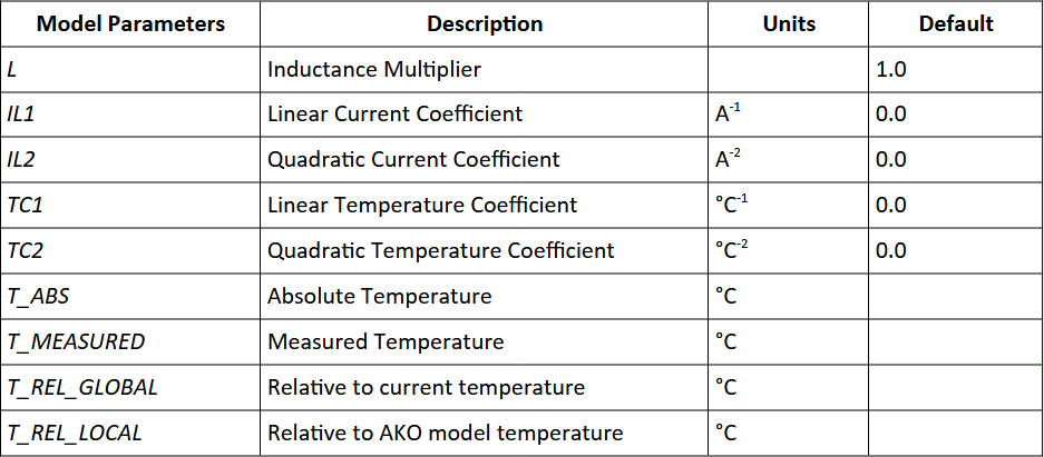
Note: A breakout resistor is essentially a resistor model with full SPICE code integration. Parameters such as tolerances, temperature coefficients, and operating temperatures can be assigned to breakout parts. The following breakout parts are included in PSpice 24.1:
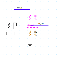
Step 6: Click to place the resistor in the schematic. Right-click and select End Mode.
Configure a Breakout Model
Step 7: To configure a breakout model, breakout parameters need to be defined in the component’s SPICE code. Right-click the breakout resistor and select Edit PSpice Model. The model file opens in the PSpice Model Editor.
Note: If the Product Choices window opens, select the appropriate license and click OK.
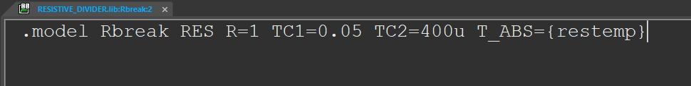
Step 8: Add the script TC1=0.05 TC2=400u T_ABS={restemp} to the line of code.
Note: This will set the linear temperature coefficient to 0.05, the quadratic temperature coefficient to 400u, and the absolute temp to a variable called {restemp}, which we will define later. The following parameters can be added to breakout parts:
Step 9: Select File > Save from the menu or the Save button from the toolbar.
Step 10: Close the PSpice Model Editor. The breakout parameters have been defined for the resistor.
Adding a Parameter List
Step 11: Reopen the Component Explorer tab.
Step 12: In the Categories list, navigate to PSpice > Simulator Command > Setup.
Step 13: Select the PARAM object. Right-click and select Place.
Note: This object acts as a list to store simulation parameters.
Step 14: Click to place the parameter list. Right-click and select End Mode.
Step 15: Double-click the list to open the Property Editor tab.
Note: Parameters are defined in the Property Editor tab.
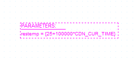
Step 16: Select New Property.
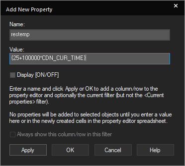
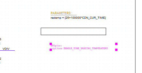
Step 17: The Add New Property window opens. Enter restemp for the name and {25+100000*CDN_CUR_TIME} for the value.
Note: This will increase the resistor temperature by 0.1°C per microsecond.
Step 18: Check Display ON/OFF and click OK.
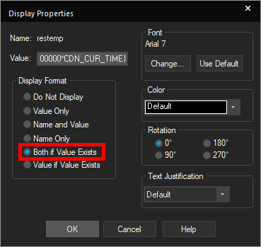
Step 19: The Display Properties window opens. Under Display Format, select Both if Value Exists and click OK. This will display the name of the parameter and its value if the value is defined.
Step 20: Click Apply and close the Property Editor tab. The restemp parameter is now visible in the Parameters list.
Model Temperature Variations
Step 21: To enable time-varying temperature, select Place > Text from the menu.
Step 22: The Place Text window opens. Enter the following script:
@PSpice:
.options ENABLE_TIME_VARYING_TEMPERATURE
Click OK.
Step 23: Click to place the text in the canvas. Right-click and select End Mode. This will enable temperature variation with time in a single simulation run.
Defining and Running the Simulation
Step 24: Select PSpice > New Simulation Profile from the menu.
Step 25: Name the profile TEMP_DIVIDER_TRANS and click Create.
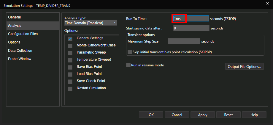
Step 26: In the Simulation Settings window, set the Run To Time to 1ms.
Step 27: Leave the other settings as the defaults and click OK.
Step 28: Select the Voltage/Level Marker button from the toolbar.
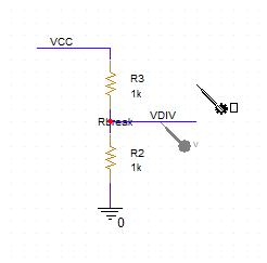
Step 29: Click to place a probe on the VDIV net. Right-click and select End Mode.
Step 30: Select PSpice > Run from the menu.
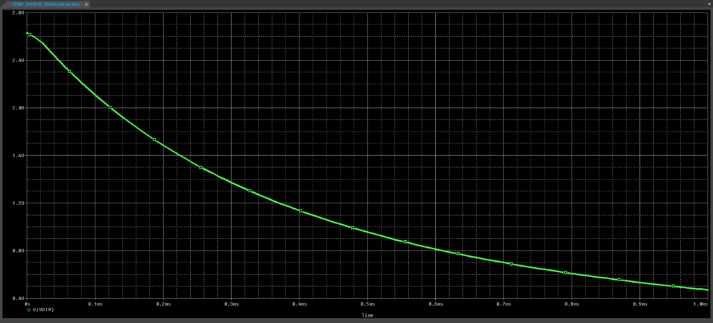
Step 31: View the simulation results. As the upper resistor of the divider heats up, its value increases, decreasing the output voltage.
Wrap Up & Next Steps
Configure a breakout model to perform realistic simulations, modelling temperature variations in a single SPICE simulation and analyzing the effect of temperature changes over time with PSpice. Upgrade to the latest 23.1 release or test out this feature and more with a free trial of OrCAD X.

