With today’s ever-increasing design complexity, circuit simulations have also become more complex often resulting in longer run times. If the circuit behavior does not meet the desired performance objectives and the circuit must be modified, the additional time spent was unnecessary and with strict time-to-market goals, excess time simulating can derail the project schedule. With assertions in PSpice, users can automatically stop circuit simulations when a voltage or current exceeds a boundary condition, saving crucial design time.
This quick how-to will provide step-by-step instructions on how to pause circuit simulation with the .WATCH function in OrCAD PSpice.
To follow along, download the files provided above the table of contents.
How-To Video

Creating a Simulation
Step 1: Open the provided design in OrCAD PSpice Designer.
Step 2: Select PSpice > New Simulation Profile from the menu.
Step 3: Name the simulation profile Buck_Converter_Trans and click Create.
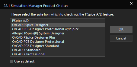
Note: If the Simulation Manager Product Choices window opens, select the appropriate license and click OK.
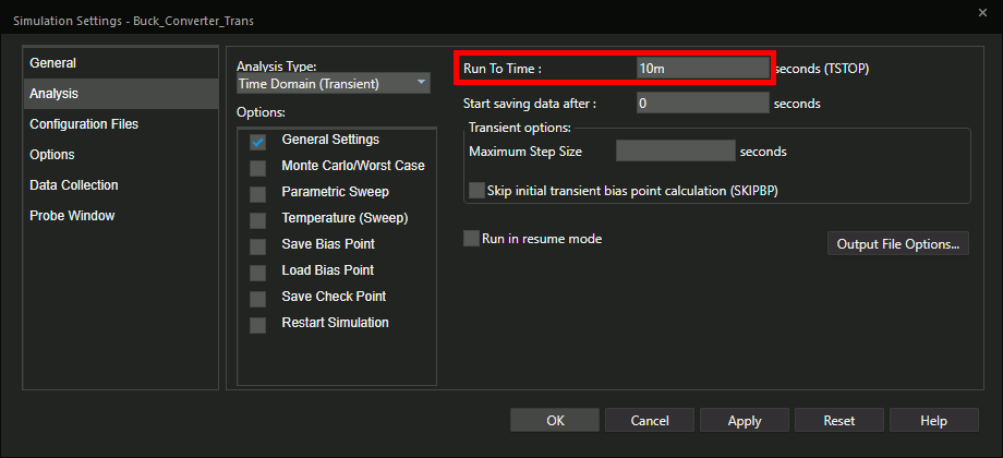
Step 4: Set the Run To Time to 10m.
Step 5: Click OK to create the simulation.
Step 6: Select the Voltage/Level Marker button from the toolbar.
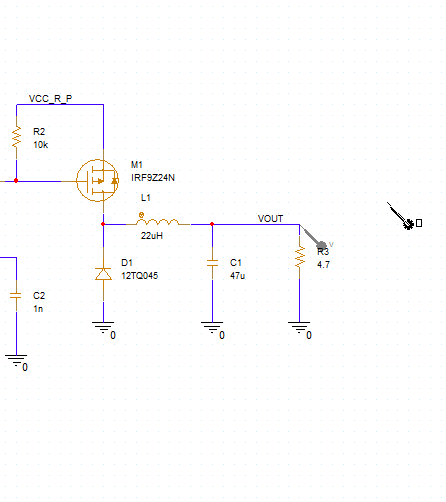
Step 7: Click to place a probe on the VOUT net. Right-click and select End Mode.
Step 8: Select PSpice > Run from the menu.
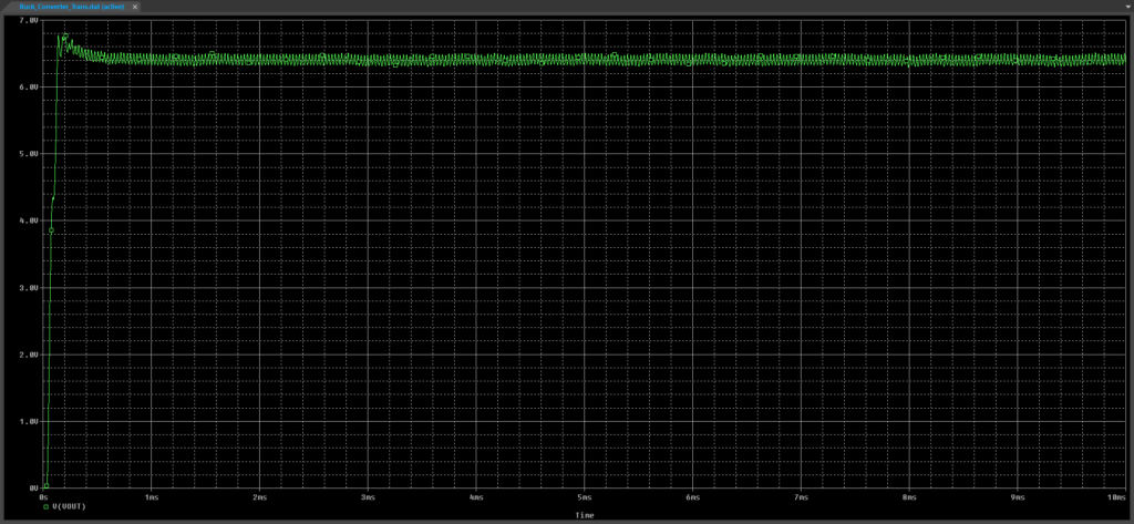
Step 9: View the simulation results. The output of the buck converter is noisy and does not hold at the desired 6V.
Step 10: Close the result window.
Adding the Assertion Code
Step 11: Back in the schematic, select Place > Text from the menu.
Step 12: Add the following text:
@PSPICE:
.WATCH TRAN V([VOUT]) (0,6.5V)
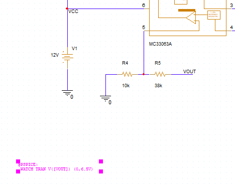
Step 13: Click OK and click to place the text in the schematic. Right-click and select End Mode.
Note: The provided files contain a text file with the assertion text which can be copied and pasted into PSpice.
Step 14: Select PSpice > Run from the menu.
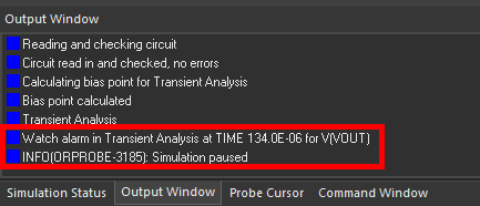
Step 15: View the result window. The simulation was paused because the watch command detected an output voltage of over 6.5V, as shown in the Output Window panel.
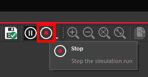
Step 16: Click Stop to stop the simulation.
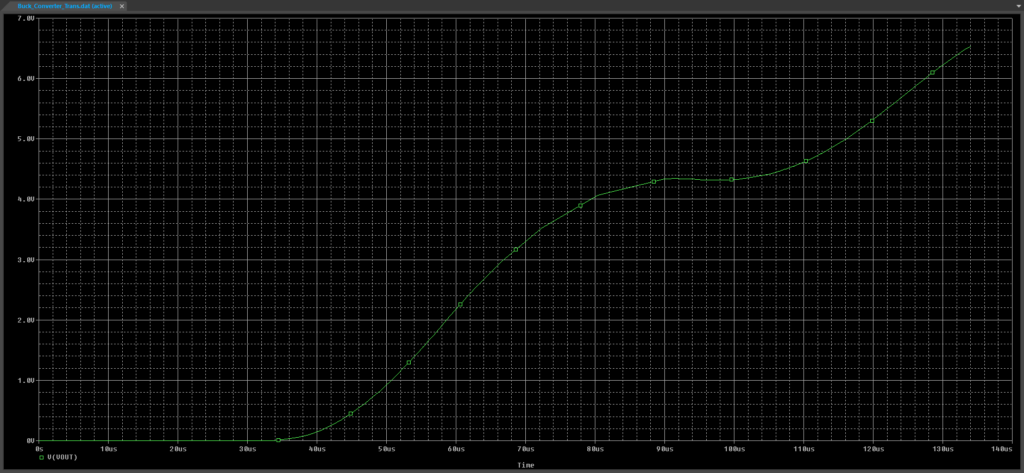
Step 17: View the plot. The simulation was run until the output voltage hit 6.5V, around 134 microseconds.
Correcting the Circuit
Step 18: Close the result window. Back in the schematic, double-click the value of inductor L1 to change it.
Step 19: Enter 47uH for the value and click OK.
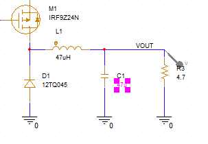
Step 20: Double-click the value for capacitor C1. Change the value to 560u and click OK.
Step 21: Select resistor R6 and press Delete on the keyboard.
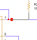
Step 22: Click and drag the wire to complete the connection.
Step 23: Double-click the value for resistor R2. Change the value to 470 and click OK.
Step 24: Select PSpice > Run from the menu.
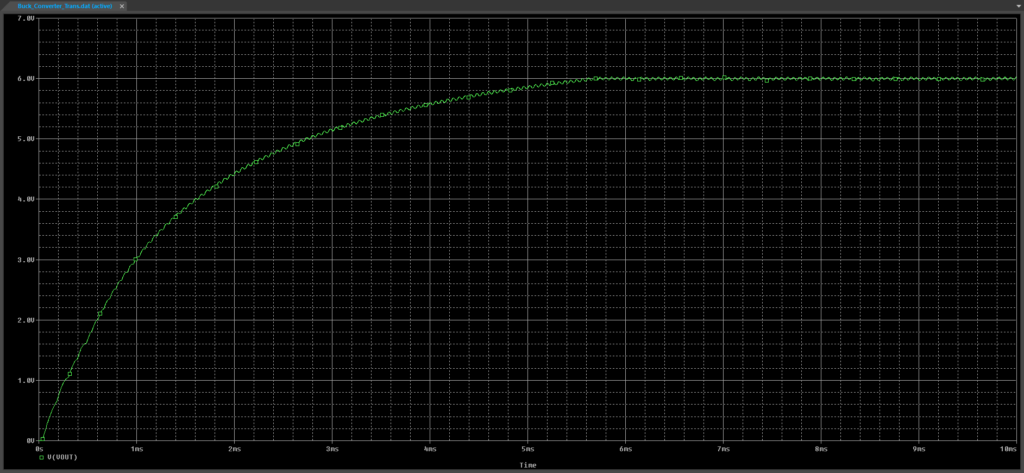
Step 25: View the results. The output voltage now stays below 6.5V and the regulator operates properly. The simulation was not paused.
Wrap Up & Next Steps
Saving time during simulation can help a project be completed on time and under budget. Quickly set boundary conditions and automatically stop lengthy simulations when performance objectives are not achieved in OrCAD PSpice. Learn how you can easily simulate, analyze, and optimize your circuit functionality with a free trial .

