When designing a PCB, it is critical to not only ensure fitment between components on the board in 2D, but to ensure they fit within the enclosure in 3D. OrCAD X Presto has a new, faster 3D modeling interface to make a full analysis easy. With this new interface, you can adjust components, view rigid-flex bends, and hide certain components for better visibility.
This quick how-to will provide step-by-step instructions on how to analyze your PCB with 3D analysis in OrCAD X Presto including:
- Viewing the board in 3D
- Adjusting 3D visibility
- Mapping mechanical models
- Moving components in the 3D view
- Bending Rigid-flex designs
To follow along, download the provided files above the table of contents.
How-To Video
 Open in New Window
Switching to 3D Mode in OrCAD X Presto
Step 1: Open the provided or desired design in OrCAD X Presto.
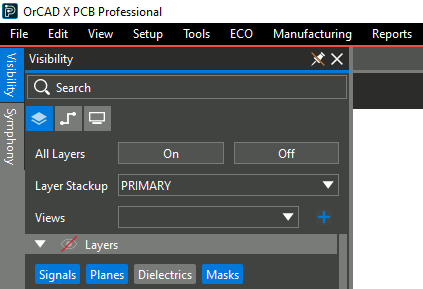
Step 2: Select Visibility on the left side of the screen to open the Visibility panel.
Note: If the button for this panel is not visible, select View > Panels > Visibility from the menu.
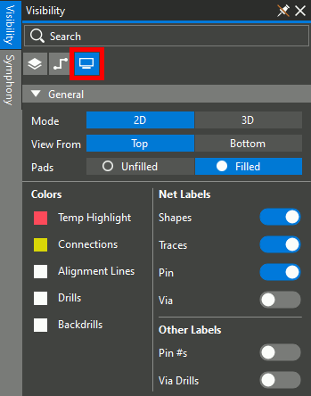
Step 3: Select the Display mode.
Step 4: Select 3D under General > Mode to set the view to 3D.
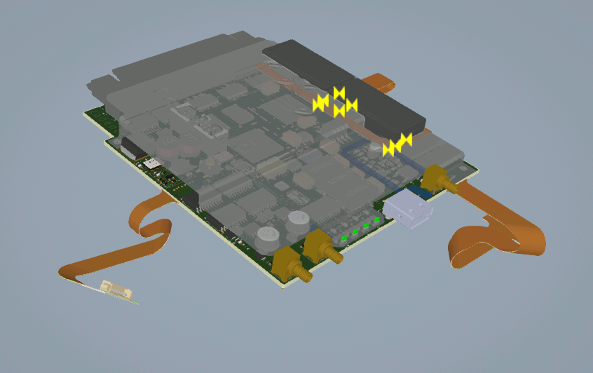
Step 5: The 3D view opens. Hold the middle mouse button and drag to pan the view. Hold the middle mouse button and Shift on the keyboard to rotate the view.
Note: If you do not have a middle mouse button, use the directional arrows on the keyboard to pan the view. Hold Shift and use the directional arrows to rotate the view.
Yellow DRC markers are shown on the LCD section of the board because, at the full bend angle, the LCD pins hit the top cover and the chips below it. The bend locations, radii, and angles can be adjusted to correct this.
Viewing 3D Component Properties
Step 6: Select a component on the 3D canvas, such as D3.
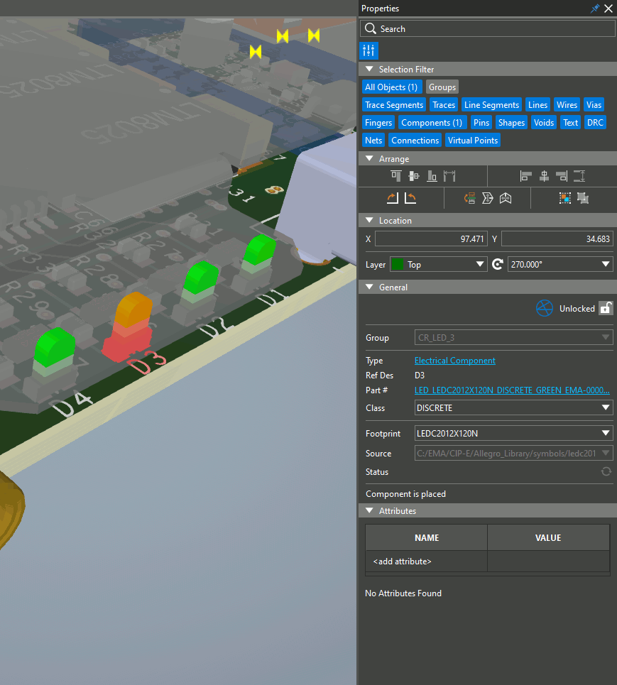
Step 7: All commands and panels have remained the same between 2D and 3D. View the Properties panel on the right side of the screen. All component properties are listed as they were in 2D.
Note: To learn how to navigate the Presto interface in 2D, check out our how-to here.
Configuring Visibility Panel in 3D
Step 8: Reopen the Visibility panel by selecting Visibility on the left side of the window.
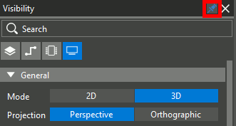
Step 9: Select the button to disable the Auto Hide feature to prevent the panel from closing.
Step 10: Select the Net mode in the Visibility panel.
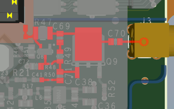
Step 11: Double-click one of the nets in the list. The net is highlighted on the board and the view is automatically panned to the top or bottom depending on the layer it is on.
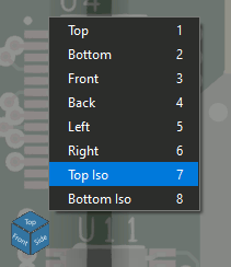
Step 12: To reset the view to isometric, select the View menu and Top Iso.
Changing Component Visibility
Step 13: Select the Component mode from the Visibility panel.
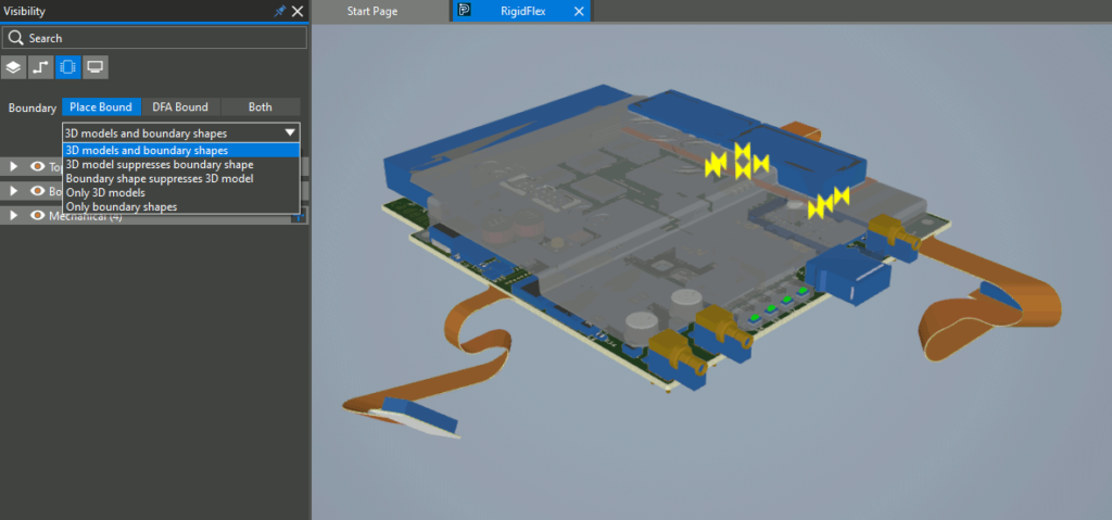
Step 14: Under Boundary, select 3D Models and Boundary Shapes from the drop-down menu to view the boundary shapes.
Note: The following options are available in this menu.
- 3D Models and Boundary Shapes: Displays 3D models with boundary shapes for all components.
- 3D Model Suppresses Boundary Shape: Displays 3D models on all components with mapped 3D models and boundary shapes for other components.
- Boundary Shape Suppresses 3D Model: Displays boundary shapes for top and bottom components and 3D models for mechanical components.
- Only 3D Models: Displays only 3D models. Components without models are not displayed.
- Only Boundary Shapes: Displays only boundary shapes.
Step 15: Select Only 3D Models from the dropdown to view only the 3D models.
Step 16: Visibility of mechanical models can also be controlled from this panel mode. Select the arrow to collapse the Top list. Expand the Mechanical list.
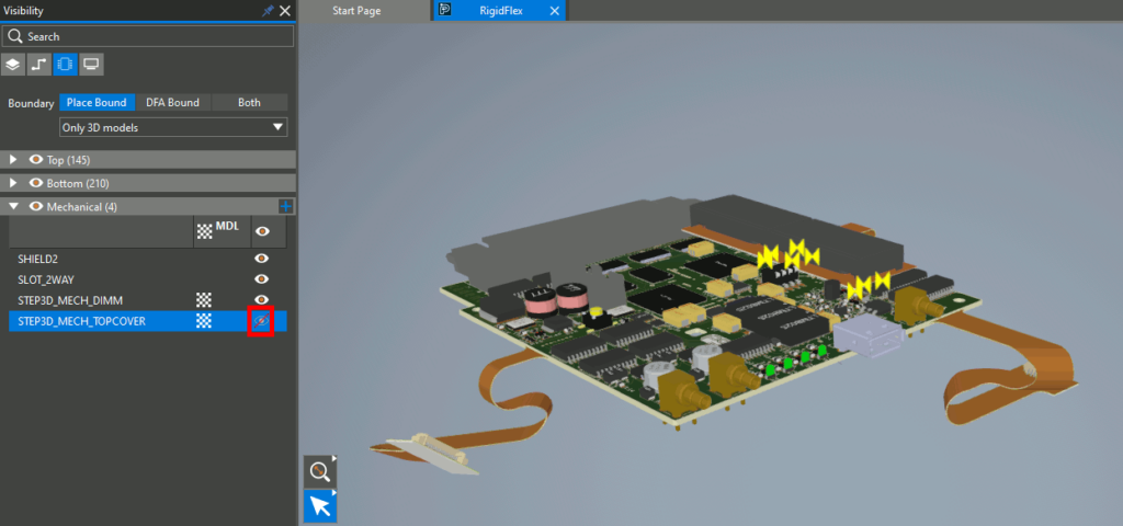
Step 17: Select the checkerbox symbol to change the transparency of the top cover.
Step 18: Select the eye for STEP3D_MECH_TOPCOVER to remove the top cover from the view.
Step 19: Visibility can be adjusted for individual components as well. Expand the Top list.
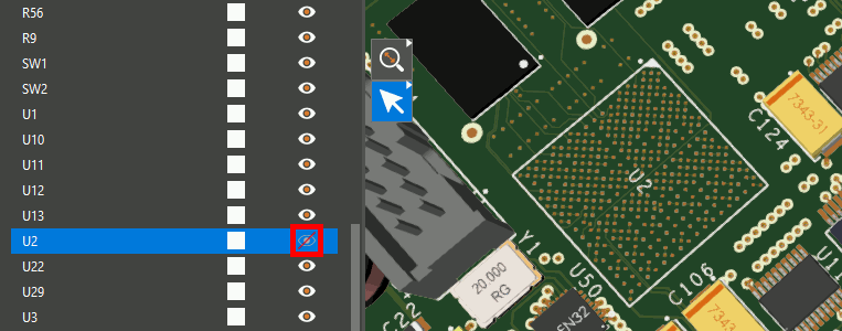
Step 20: Scroll down and select the eye for U2. U2 is hidden, leaving its BGA array footprint visible on the board.
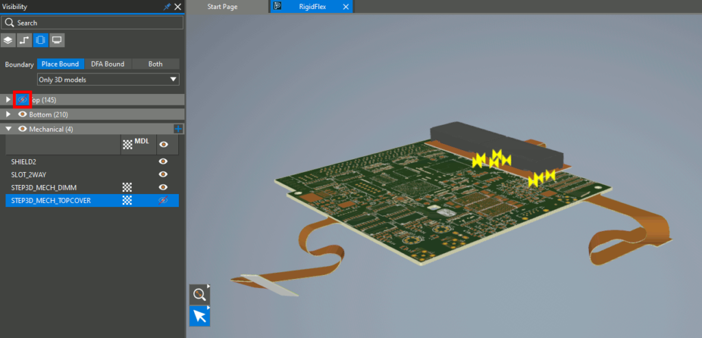
Step 21: Select the eye for the TOP category to remove all top components.
Adding Mechanical Symbols in OrCAD X Presto
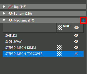
Step 22: To add a new mechanical symbol to the 3D view, such as an enclosure or connector, select the plus sign in the Mechanical header.
Step 23: Browse to a STEP file of a mechanical model. Select the file and click Open.
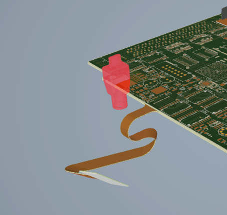
Step 24: The model is imported into the 3D canvas. Select the model.
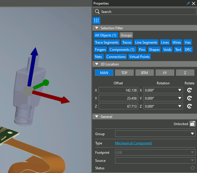
Step 25: View the Properties panel. Options are available to map the symbol as needed.
Note: Mapping can be performed with:
- Click-and-drag manual adjustment in the X, Y, and Z directions
- Locking the model to the top or bottom of the footprint
- Snapping 3D features to pads or footprint features
- Adjusting the X, Y, and Z coordinates numerically
To learn how to map 3D models to component footprints, view our how-to here.
Step 26: Since an extra symbol is not needed in this design, right-click the listing in the Visibility panel and select Delete.
Moving a Component in 3D
Step 27: Select the eye for Top to re-enable visibility for top components. Select the eye for Mechanical to turn off all mechanical components.
Step 28: Select a component on the board. The Properties panel is populated with component properties.
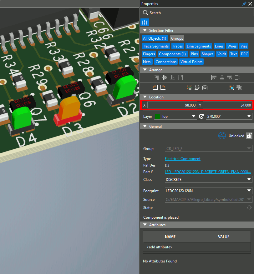
Step 29: Enter new values into the Location X and Y fields. The component is moved with its 3D model.
Analyze Your PCB in 3D: Rigid-Flex Bends
Note: In a rigid-flex board, bends can be previewed in the 3D canvas. If you do not have a rigid-flex board, one is provided in the files above the table of contents.
Step 30: Select the Display mode in the Visibility tab.
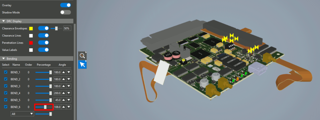
Step 31: Scroll down and click and drag each slider listed under Bending to adjust the rigid flex bends.
Step 32: Click and drag the slider for All to adjust all bends on the board simultaneously.
Wrap Up & Next Steps
Quickly analyze your PCB in 3D with the new 3D engine in OrCAD X Presto. Test out this feature and more with a free trial of OrCAD. For more how-tos and step-by-step walk throughs, visit EMA Academy.