SPICE simulation can be used to verify circuit functionality before production; however, standard SPICE simulation doesn’t take design longevity and reliability into consideration. To ensure design reliability and prevent field failures, the load on components, or component stress, should be analyzed to pinpoint and correct design weaknesses. With PSpice Designer easily analyze component stress to ensure that the right components are selected for your design and improve PCB reliability with Smoke Analysis.
This quick how-to will provide step-by-step instructions on how to analyze component stress with smoke analysis in PSpice Designer.
How-To Video
[coming soon]
Loading a Demo Design
Step 1: Open PSpice Designer.
Step 2: Select File > Open > Demo Designs from the menu.
Step 3: The Open Demo Designs window opens. Scroll down and select RF Amplifier.
Step 4: Click Open to open the design.
Note: If this design has been modified on your system, download the clean version provided above the table of contents.
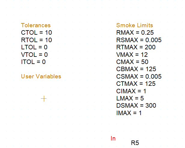
Step 5: View the Tolerances and Smoke Limits in the schematic canvas. Ensure that the values listed match those shown in the picture above.
Running a Transient Analysis
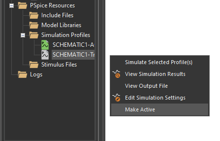
Step 6: A transient analysis must be run for stress analysis. In the Project Manager, under PSpice Resources > Simulation Profiles, right-click SCHEMATIC1-Tran and select Make Active.
Note: This will change the active simulation to a transient analysis.
Step 7: Select PSpice > Run from the menu to start the simulation.
Note: The simulation is pre-defined in this example. To learn how to configure and run a new simulation in PSpice, see our how-to here.
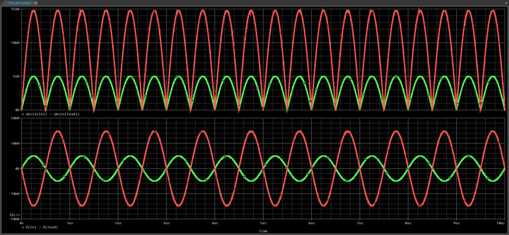
Step 8: View the transient simulation results. The input and load voltages are shown in original and rectified form.
Step 9: Close the PSpice A/D window.
Analyze Component Stress with PSpice
Step 10: Back in Capture, select PSpice > Advanced Analysis > Smoke from the menu.
Note: If the PSpice Advanced Analysis Product Choices window opens, select the appropriate license and click OK.
Smoke Analysis calculates safe operating limits using component parameter maximum operating conditions and derating factors.
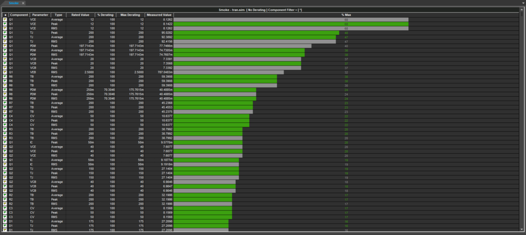
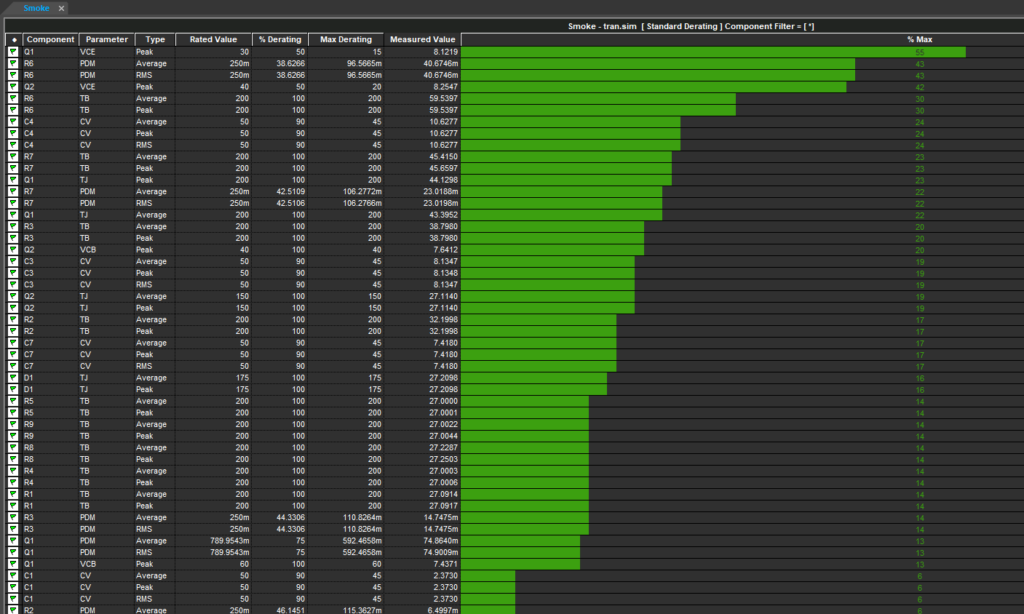
Step 11: A Smoke Analysis simulation was performed with the transient analysis. View the simulation results. Green bars show values within 90% of the safe operating limits, while gray bars indicate invalid values.
Step 12: Right-click in the Smoke Analysis result table and select Hide Invalid Values to remove all invalid values from the table.
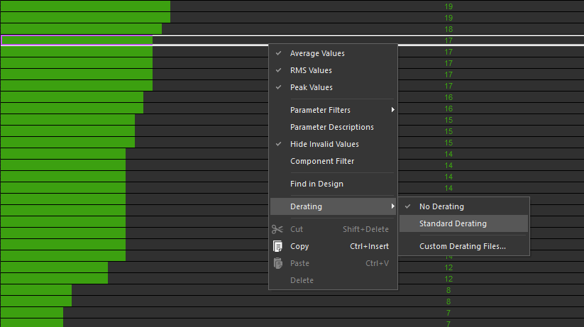
Step 13: Right-click in the table and select Derating > Standard Derating to change the component derating.
Step 14: Select Run > Start Smoke from the menu to re-run the analysis.
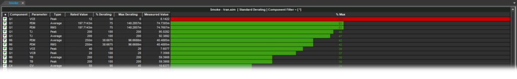
Step 15: View the result. The VCE of Q1 is shown to be out of its safe operating range, as indicated by a red bar.
Replacing a Component Under Stress
Step 16: To correct the out-of-range result, Q1 can be replaced. Right-click a cell in the row for Q1 VCE and select Find in Design.
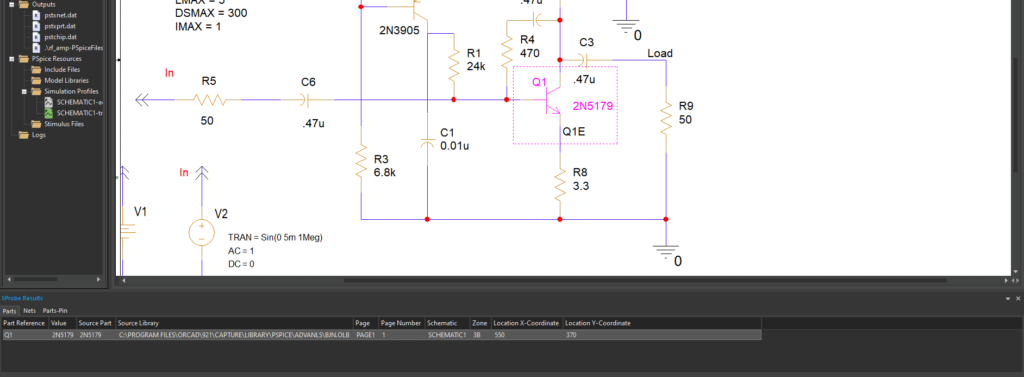
Step 17: Minimize the Advanced Analysis window and return to the schematic canvas. Transistor Q1 is highlighted. An XProbe Results panel is visible with Q1 listed. Double-click the listing to be brought to its location.
Step 18: Press Delete on the keyboard to delete the transistor.
Step 19: To place a new transistor, select Place > Component from the menu.
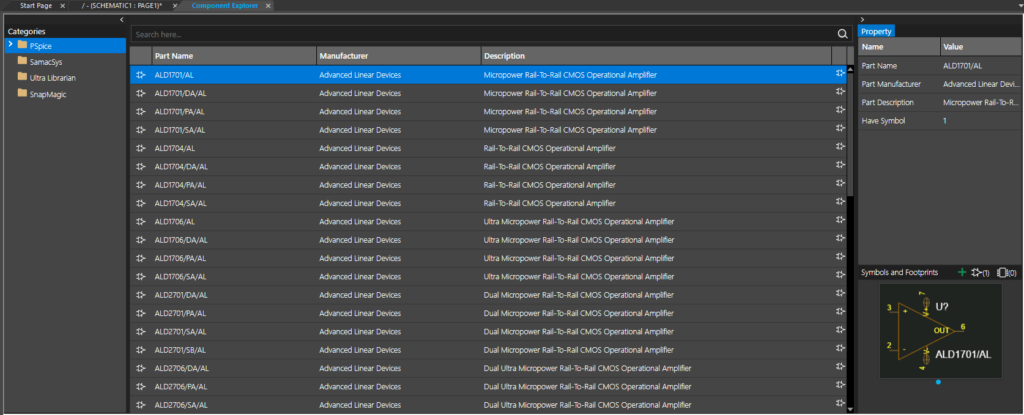
Step 20: The Component Explorer tab opens. Here you can place components with pre-defined SPICE models as well as components from SamacSys, Ultra Librarian, and your personal workspace. Select the PSpice category.
Step 21: Enter 2N2219 into the Search field and press Enter to search.
Step 22: Select 2N2219 from the list. Double-click the listing to attach the component to your cursor.
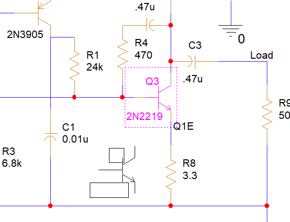
Step 23: Click to place the transistor where Q1 was. Right-click and select End Mode.
Step 24: Double-click the reference designator to change it.
Step 25: Enter Q1 for the value and click OK.
Running the Analysis
Step 26: After replacing a component, the transient analysis must be re-run before smoke analysis can be performed. Select PSpice > Run from the menu.
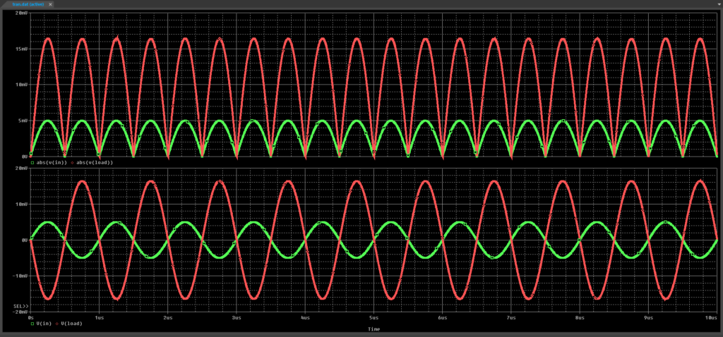
Step 27: View the simulation results. The amplitude of the plotted output is slightly higher than it was before.
Close the PSpice A/D window.
Step 28: Reopen the PSpice Advanced Analysis window (with the previous smoke analysis results).
Step 29: Select Run > Start Smoke from the menu.
Step 30: View the results. All bars are now green, indicating that all components are now operating within their safe limits.
Wrap Up & Next Steps
Quickly analyze component stress to ensure reliable circuit behavior and that all components operate within their limits using Smoke Analysis in PSpice Designer. Test out this feature and more with a free trial of OrCAD. Want to learn more about Smoke Analysis and the other advanced analysis options in PSpice? View the Level 1 and Level 2 PSpice Advanced Analysis Workshops.
