The OrCAD X Footprint Editor is a modern and powerful application to build your PCB footprints including efficient methods to add pins to a footprint. Within the footprint editor, the Properties panel provides easy access to all relevant data about a footprint, including:
- Number of Electrical Pins by Type
- Number of Mechanical Pins
- Reference Designator
- Quick access to 3D Model
- List of Padstacks with Options to Update and Replace
- Integrated Change History Log
When you add pins to a footprint, OrCAD X allows you to search your padstack library while viewing the rich set of padstack parameters and their dimensions to quickly determine which padstack you should use in your design.
This quick how-to will provide step-by-step instructions on how to add pins to a footprint with the footprint editor in OrCAD X Presto.
How-To Video
 Open in New Window
Selecting a Padstack
Step 1: Open the desired footprint in OrCAD X Presto.
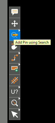
Step 2: Select the Add Pin Using Search mode from the toolbar.
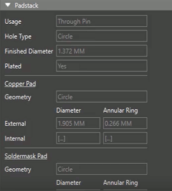
Step 3: The Search panel opens with a list of padstacks. Select a padstack. In the Properties panel, padstack parameters as well as dimensions are visible to help you efficiently determine which padstack to use for the footprint.
Step 4: Double-click the padstack row to place the padstack in the design.
Creating a Padstack
Note: If the ideal padstack is not found, a padstack can be created parametrically using industry standard surface mount and through hole pin types.
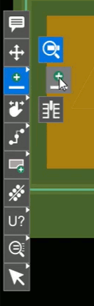
Step 5: Right-click Add Pin Using Search in the toolbar and select Add Pad Wizard to start the wizard.
Step 6: Select the desired pin shape. Available options for surface-mount padstacks include:
- Circle
- Square
- Oblong
- Rectangle
- Rounded Rectangle
- Chamfered Rectangle
Available options for through-hole pins include:
- Circle
- Oval Slot
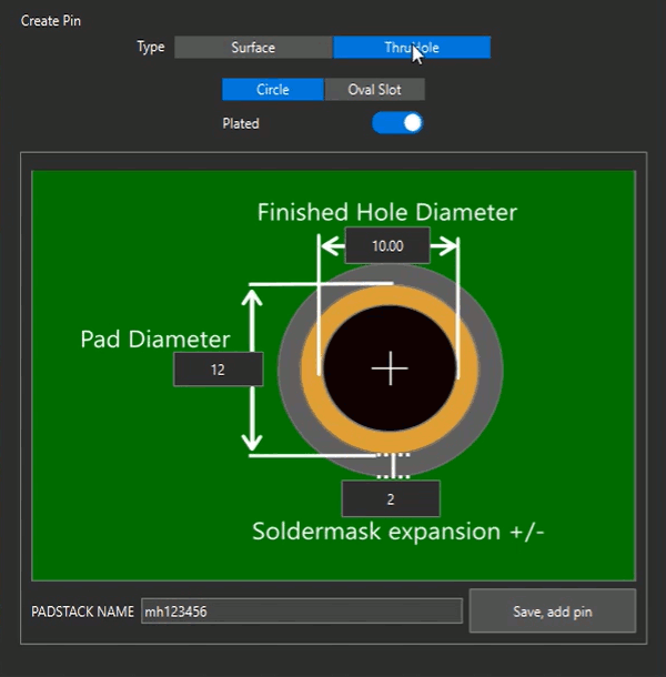
Step 7: Enter the desired dimensions in the Create Pin window.
Note: Dimensions available will vary depending on the type of pin. Common dimensions include:
- Width/Height for non-square pads
- Diameter for circular pads
- Soldermask and solderpaste expansion

Step 8: Enter a name for the padstack and click Save, Add Pin to add the pin to the design.
Add Pins to a Footprint
Step 9: Click to place the pins in the footprint design. Press Escape on the keyboard when finished.
Note: Pin placement will use the adjustable pin grids or the configured snapping options.
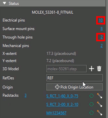
Step 10: View the Properties panel. The pin count has been updated.
Wrap Up & Next Steps
Quickly create the pins and footprints required for your design in the Footprint Editor in OrCAD X Presto. Test out this feature and more with a free trial of OrCAD X Presto. For more how-tos and step-by-step walk-throughs, visit EMA Academy.