Ensuring schematic design intent before proceeding to the PCB layout is crucial step in the PCB design process to guarantee a functional end design. If a mistake is made during the schematic, such as an incorrect or incomplete net connection, it may not be caught during the PCB layout process. OrCAD X Capture allows you to configure and perform a schematic design rule check to ensure your design intent is communicated accurately.
This quick how-to will provide step-by-step instructions on how to perform a schematic design rule check in OrCAD X Capture.
To follow along, download the provided files above the table of contents.
How-To Video
 Open in New Window
Configuring Design Rule Check (DRC) Options
Step 1: Open the provided design in OrCAD Capture.
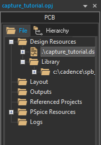
Step 2: Select capture_tutorial.dsn in the Project Hierarchy.
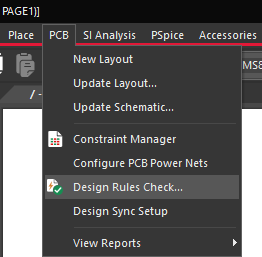
Step 3: Select PCB > Design Rules Check from the menu.
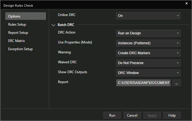
Step 4: In the Options tab, under Batch DRC, select Run on Design from the DRC Action drop-down menu.
Step 5: Select Instances (Preferred) from the Properties (Mode) dropdown.
Note: If you have a hierarchical design, select Occurrences for this setting.
Step 6: Select Create DRC Markers from the Warning dropdown.
Step 7: Select Do Not Preserve from the Waive DRC dropdown.
Step 8: Select DRC Window from the Show DRC Outputs dropdown.
Step 9: Select the ellipsis for Report to open the file browser.
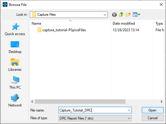
Step 10: Browse for a location to save the report. Enter a name for the file and click Open.
Note: The report is saved as a plain-text file.
Additional DRC Settings
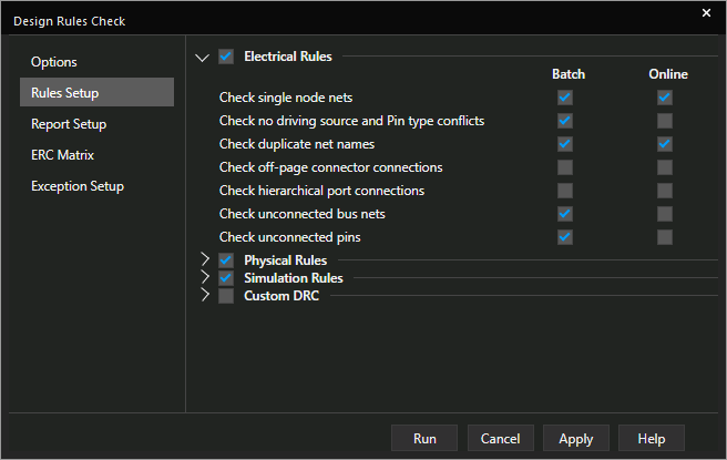
Step 11: Select the Rules Setup tab on the left side of the window. Here you can configure which electrical, physical, and simulation rules are included in the design rule check.
Note: Rules with the Online option checked are checked in real-time. Rules with the Batch option checked are checked when the DRC check is run.
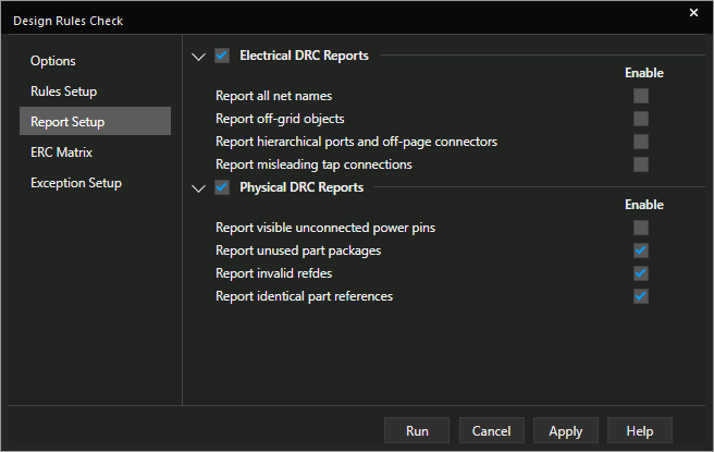
Step 12: Select the Report Setup tab. Here you can choose which aspects of the check to report.
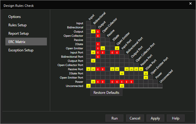
Step 13: Select the ERC Matrix tab. Here you can configure which violations are flagged as warnings and which are flagged as errors.
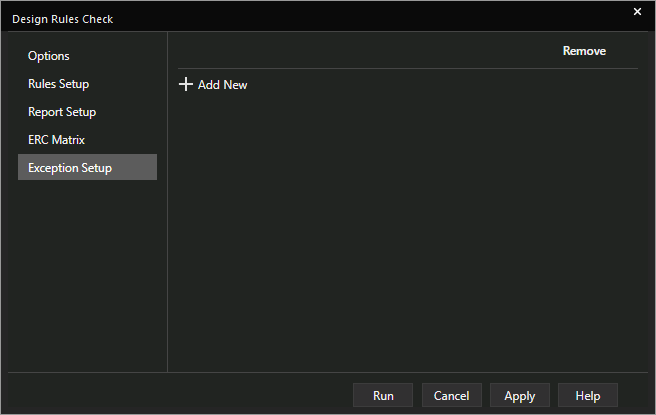
Step 14: Select the Exception Setup tab. Here you can configure exceptions.
Step 15: Select the Options tab to return to the Options panel.
Perform a Schematic Design Rule Check
Step 16: To perform a schematic design rule check, select Run.
Step 17: A prompt will appear that this will clear the Undo/Redo cache. Click Yes to accept.
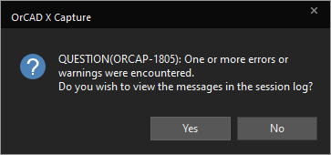
Step 18: When the check is complete, another prompt will appear that one or more errors or warnings were encountered. Click No to keep the session log closed.
Note: Click Yes to open the Session Log tab, which lists the errors in text form.
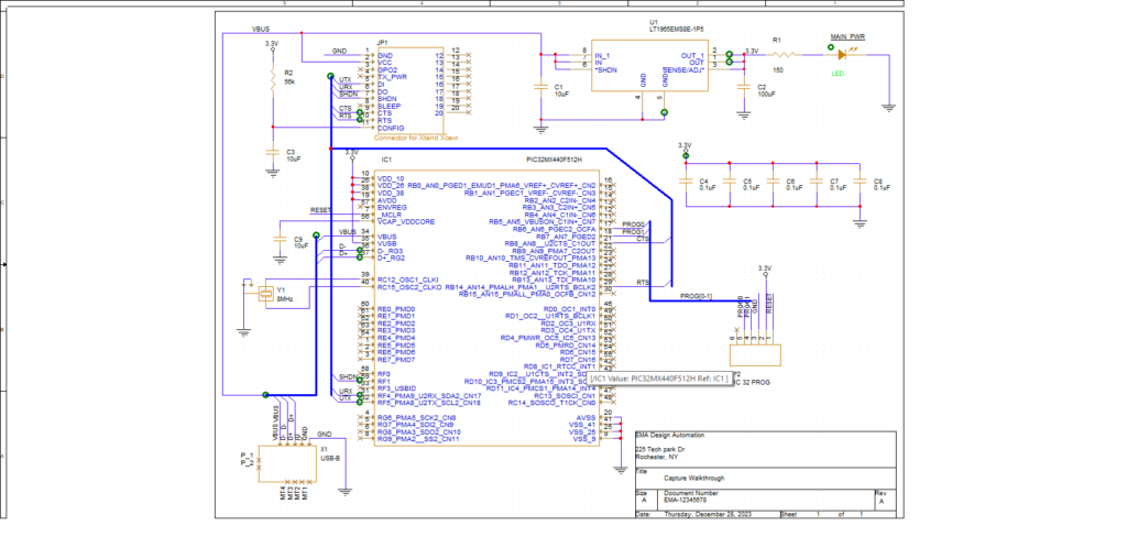
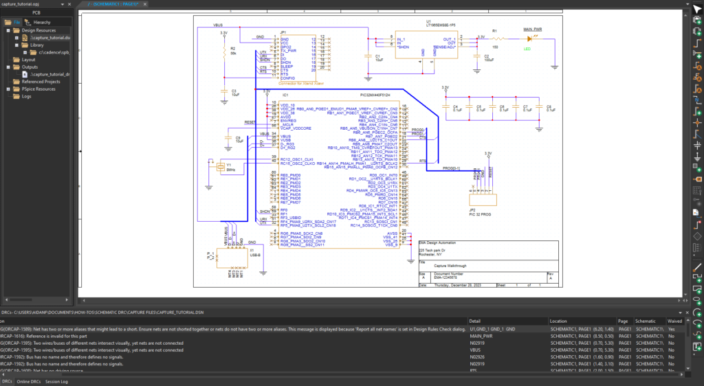
Step 19: View the schematic. Areas of concern are marked with a green marker.
Step 20: Hold CTRL and scroll up to zoom into the board.
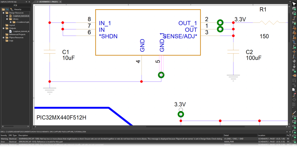
Step 21: Double-click the first error listed to be brought to the location of the marker.
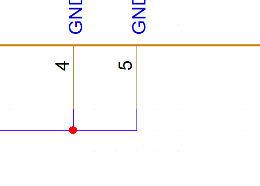
Note: This warning is for a potential short between two nets, GND and GND_1 on IC U1. Since these are the same net, a short is expected, and this warning can be ignored.
Waiving a Design Rule Error
Step 22: Left-click to select the DRC marker.
Step 23: Right-click the marker and select Waive DRC.
Step 24: Click anywhere on the board to deselect the marker. The marker disappears.
Step 25: Select PCB > Design Rules Check from the menu.
Step 26: Select Preserve from the Waive DRC dropdown. This will preserve the waived DRCs and update the list.
Step 27: Select Run to run the DRC check.
Note: Click Yes to accept any prompts that appear.
Step 28: Click No to not open the Session Log.
Note: If you accidentally open the Session log, click the DRCs tab to return to the more detailed table.
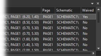
Step 29: Scroll to the right side of the table. Waived now has a value of Yes for the first row, indicating that the DRC was waived. Repeat these procedures as needed to correct/waive any errors in your design.
Clearing the DRC Markers
Step 30: Select PCB > Design Rules Check from the menu.
Step 31: Select Delete DRC Markers from the DRC Action menu.
Step 32: Select Run. Select Yes for any prompts that appear.
Step 33: Hold CTRL and scroll down to zoom out to view the design. The DRC markers have been removed, but the DRCs table remains populated.
Wrap Up & Next Steps
Perform a schematic design rule check to quickly find design errors and guarantee the accuracy of your schematics with OrCAD X Capture. Test out this feature and more with a free trial of OrCAD. Want to learn more about Capture? Get access to free how-tos, courses, and walk-throughs at EMA Academy.
