To improve understanding of design elements and schematic readability, you should deploy consistent methods for schematic symbol creation. With EDABuilder you can create a style template and automatically apply settings to component models on export to create a coherent CAD library. This method will ensure:
- Critical symbol properties are displayed
- Properties or attributes are consistently in the same location
- Symbols are created with the same colors, fonts, and spacing to improve readability
This quick how-to will provide step-by-step instructions on how to create a style template in EDABuilder to create consistency throughout schematic symbols in your designs.
To follow along, download the provide files above the table of contents.
How-To Video
 Open in New Window
Create a Style Template in EDABuilder
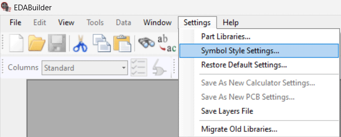
Step 1: Open EDABuilder and select Settings > Symbol Style Settings.
Note: Style settings can only be configured when no symbols are open. Make sure any symbols or projects are closed before activating Symbol Style Settings. The settings are divided into two sections:
- Graphics: Style settings for symbol graphics
- Properties: Style settings for symbol attributes or properties
Step 2: Ensure OrCAD_Capture is selected as the current style and select Save As.
Note: If you are using a different CAD tool, select the desired CAD tool style setting from the drop-down selection. This will outline the properties and options available for configuration.
Step 3: Enter a name for the new Style Template, such as Company Preferences, and select Save.
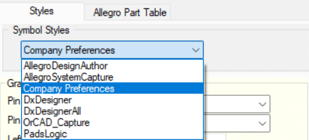
Step 4: Expand the Symbol Style Preferences dropdown and select Company Preferences.
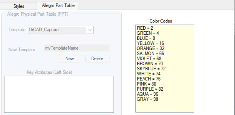
Note: If Allegro System Capture or Allegro Design Authoring is selected as the style, you can also configure a template for the Allegro Part Table.
Create a Style Template in EDABuilder: General Graphic Settings
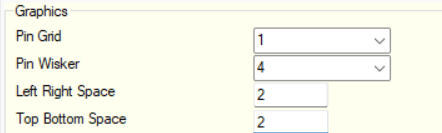
Step 5: Set the Pin Grid to 1.This configures the granularity in which pins can be placed on the schematic symbol.
Step 6: Set the Pin Wisker to 4. This configures the length of the pins on the schematic symbol in respect to the pin grid.
Step 7: Set the Left Right Space to 2. This configures the space (number of grids) required from the top when the first pin is assigned on the left or right side.
Step 8: Set the Top Bottom Space to 2.This configures the space (number of grids) required from the left when the first pin is assigned on the top or bottom side.
Create a Style Template in EDABuilder: Symbol Body Settings
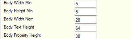
Step 9: Set the Body Width Min to 5. This configures the minimum allowed width for the body of the schematic symbol.
Step 10: Set the Body Height Min to 5. This configures the minimum allowed height for the body of the schematic symbol.
Step 11: Set the Body Width Nom to 20. This configures the standard width for the body of the schematic symbol. Any generated symbol will have this value as the default starting value.
Note: Body Text Height and Body Property Height are typically not used in the Symbol Body creation and can be left at the default values.
Create a Style Template in EDABuilder: Symbol Pin Settings
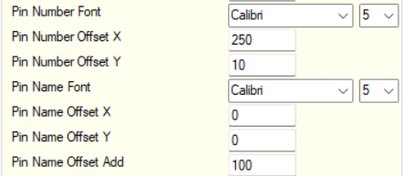
Step 12: Set the Pin Number Font. From the Font drop-down menu select Calibri. From the size drop-down menu select 5.
Step 13: Set the Pin Number Offset X to 250. This configures theoffset of the pin number in the X direction.
Step 14: Set the Pin Number Offset Y to 10. This configuresthe offset of the pin number in the Y direction.
Step 15: Set the Pin Name Font. From the Font drop-down menu select Calibri. From the size drop-down menu select 5.
Step 16: Set the Pin Name Offset X to 0. This configures the offset of the pin name in the X direction.
Step 17: Set the Pin Name Offset Y to 0. This configuresthe offset of the pin name in the Y direction.
Step 18: Set the Pin Name Offset Add to 100. This configures the offset that is added to the display pin name when the pin function is clock.
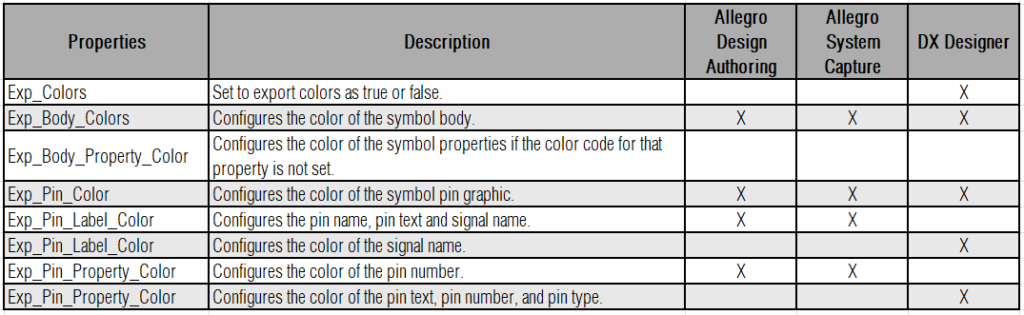
Note: Export properties are not typically used in OrCAD Capture exports. The following table provides the properties, definitions, and software in which the export property is applicable:
Appropriate values for color definitions can be found by selecting the Allegro Part Table tab.
Create a Style Template in EDABuilder: Symbol Properties
Note: Styles can be defined for each property or attribute of the schematic symbol. By default, the following properties are defined for the schematic symbol:
- Part Reference
- Value
- PCB Footprint
- Description
- Name
These property definitions are only applied to the creation of new schematic symbols. To edit properties on an existing symbol, right-click on the graphics panel and select Edit Symbol Properties.
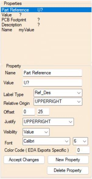
Step 19: Select Part Reference from the list of available properties. Review the configured property settings.
Step 20: Change Relative Origin and Justify to UPPERRIGHT. This will display the property in the upper right corner of the schematic symbol.
Step 21: Ensure the Visibility to Value. This will display only the value of the property on the schematic symbol.
Note: In Allegro System Capture, Allegro Design Authoring, and DX Designer this field is replaced with a Height property which configures the height of the font.
Step 22: Set the Font to Calibri and the size to 6.
Step 23: Select Accept Changes.
Note: Other configurable property options include:
- Label type: Category or type of label.
- Offset: X, Y offset with respect to relative origin to display the property name/value.
- Justify: Aligns the property text.
- Color Code: Color of the property. This field is only used in a DX Designer export.
This process should be repeated to modify any properties or attributes you want displayed on the schematic symbol. To create a new property, select New Property and define the desired settings.
Create a Style Template in EDABuilder: Additional Options
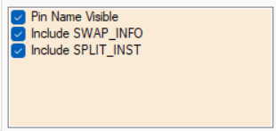
Step 24: Additional Options are available when configuring an OrCAD_Capture style. Check the box for Pin Name Visible. This will display the pin names on the schematic symbol.
Step 25: Check the box for Include SWAP_INFO. This will include SWAP_INFO as a tyle property with the symbol export, allowing the swapping of pins across split symbols in the Allegro X PCB Editor.
Step 26: Check the box for Include SPLIT_INST. This will include SPLIT_INST as a style property with the symbol export, allowing schematic symbols to be split.
Step 27: Select Save. A prompt will appear informing you that selecting Save will overwrite the style file. Select Yes.
Step 28: Close the Style Editor window.
Apply a Style Template in EDABuilder
Step 29: Select File > Open > Part.
Step 30: Select Browse. Browse to the location of the provided symbol and click OK.
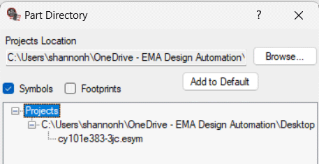
Step 31: Expand the project hierarchy and select the symbol, cy101e383-3jc.esym.
Step 31: In the Style drop-down select Company Preferences.
Step 32: The check form will appear reporting any errors or warnings found within the schematic symbol. For this example, the warning is acceptable. Select Close.
Export a Schematic Symbol with EDABuilder
Step 33: Select File > Export > OrCAD Capture Symbols.
Step 34: A prompt will appear to save the project. Select Yes.
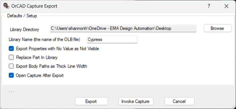
Step 35: Select Browse. Browse to the desired library directory and click OK.
Step 36: Enter a name for the library.
Step 37: Select Open Capture After Export. This will launch OrCAD Capture after the export is complete to view the symbol.
Step 38: Select Export.
Step 39: Once export is complete, a prompt appears to select your OrCAD software. Select OrCAD Capture or your desired software package and click OK.
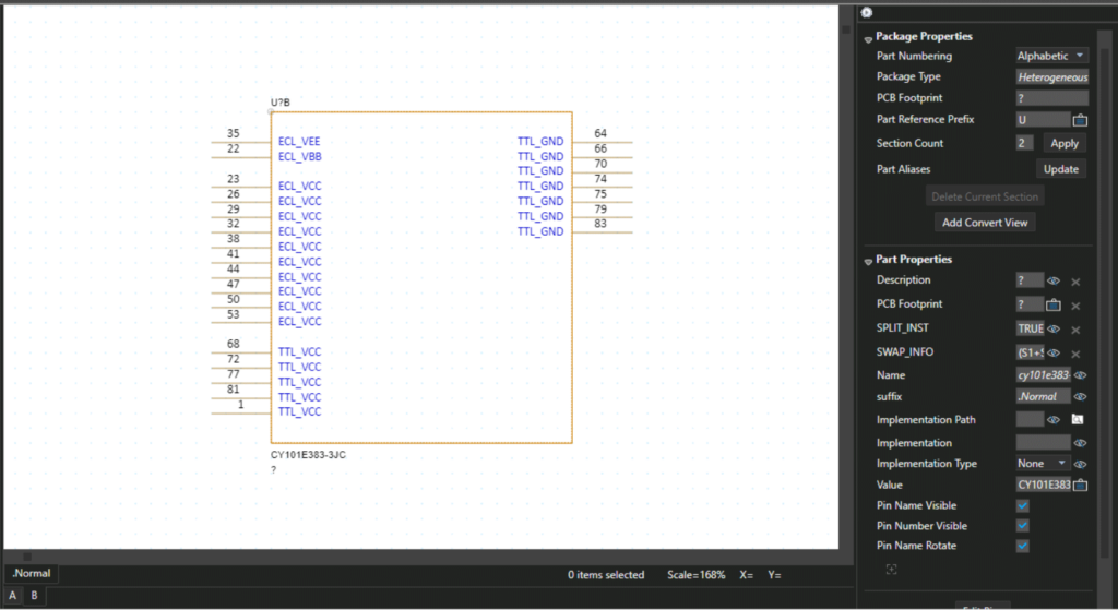
Step 40: Double-click the schematic symbol in the project hierarchy and view the completed symbol. The style template has been applied during the export.
Wrap Up & Next Steps
Create a style template in EDABuilder to automatically apply settings to component models on export, create consistent schematic symbols, and create a coherent CAD library. Get more step-by-step instructions for EDABuilder at EMA Academy.

